Vehicle transaxle

Pending Publication Date: 2022-05-12
TOYOTA JIDOSHA KK
View PDF0 Cites 2 Cited by
  • Summary
  • Abstract
  • Description
  • Claims
  • Application Information

AI Technical Summary

Benefits of technology

[0014]In the vehicle transaxle according to the first aspect of the present disclosure, (b) the resonator has the cavity and the opening. The cavity is formed between the transaxle case and the first facing wall of the first housing case, the first facing wall facing the transaxle case. The opening is formed such that the cavity is partially opened to the lateral side through the opening. (c) The volume of the cavity and the volume of the opening are set such that the resonance frequency of the resonator is lower than the natural frequency of the first facing wall of the first housing case. Since the resonance frequency of the resonator is lower than the natural frequency of the first facing wall, even when the first facing wall vibrates at the natural frequency, the cavity does not resonate. Hereby, abnormal noise caused from the vehicle transaxle can be reduced.
[0015]In the vehicle transaxle of the second aspect of the present disclosure, (a) the second housing case in which the se

Problems solved by technology

In the meantime, in the vehicle transaxle, vibrations may be caused from the DC/DC converter, for example, by a switching operation on the switching element.
Accordingly, when a wall constituting the first housing case resonates by being excited by the vibrations caused from the DC/DC converter, for exa

Method used


Image

  • Vehicle transaxle
  • Vehicle transaxle
  • Vehicle transaxle

Examples


Example

Embodiment 1

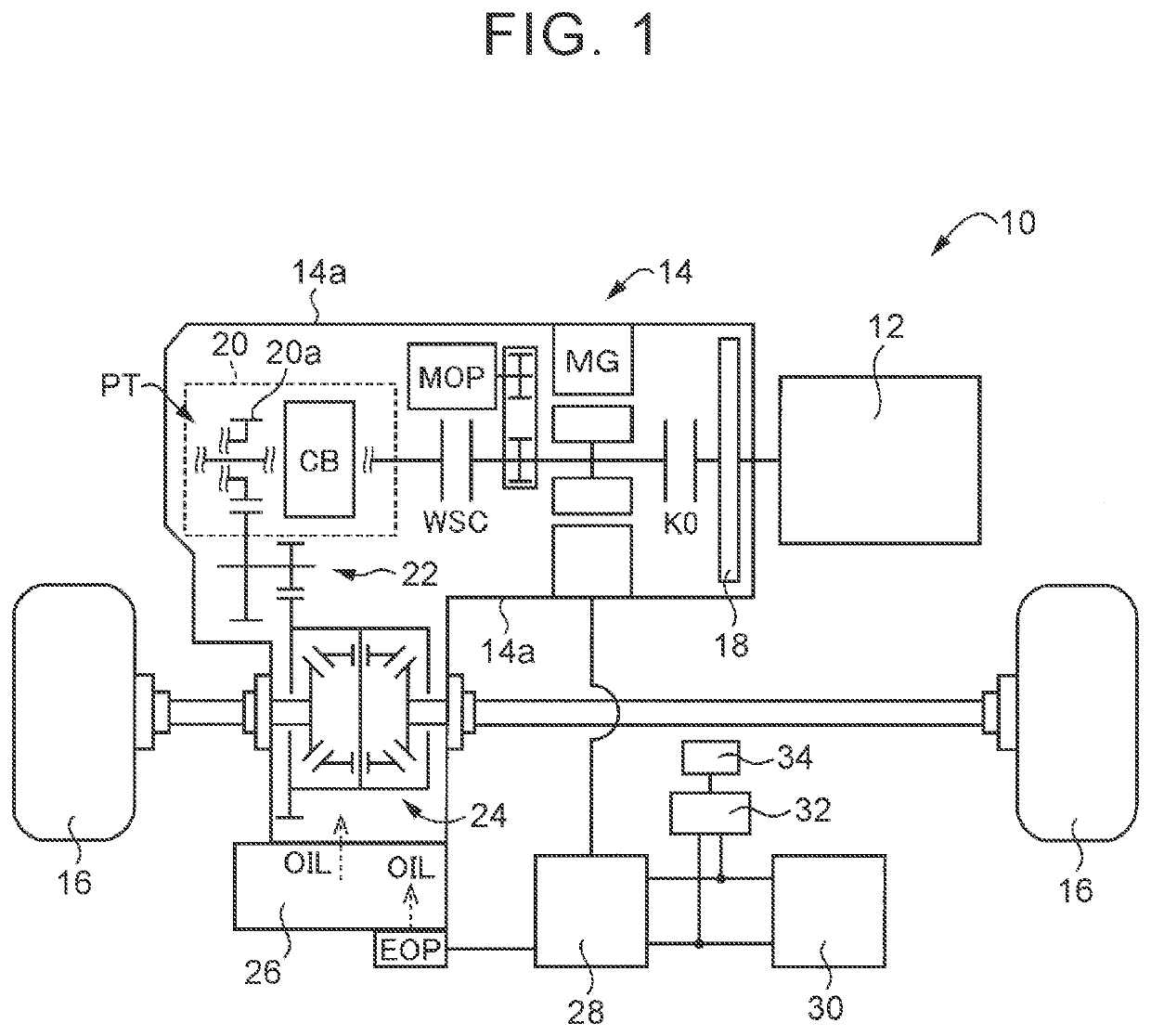
[0032]FIG. 1 is a view to describe a schematic configuration of a vehicle 10 to which the present disclosure is applied. As illustrated in FIG. 1, the vehicle 10 includes an engine 12, a transaxle (a vehicle transaxle) 14 made of light metal, and driving wheels 16. As illustrated in FIG. 1, the transaxle 14 is configured such that a damper 18, a disconnection clutch K0, an electric motor (a vehicle driving electric motor) MG, a start clutch WSC, an automatic transmission 20, and so on are accommodated in a transaxle case 14a that is a nonrotatable member attached to a vehicle body. Further, the transaxle 14 is configured such that a reduction gear mechanism 22 connected in a power transmittable manner to a transmission output gear 20a as an output rotational member of the automatic transmission 20, a differential gear 24 connected in a power transmittable manner to the reduction gear mechanism 22, and so on are accommodated in the transaxle case 14a. Note that the damper...

Example

Embodiment 2

[0051]FIG. 5 is a view to describe a resonator 60 provided in a transaxle of another embodiment of the present disclosure and functioning as a Helmholtz resonator. The transaxle of the present embodiment is different from the transaxle 14 of Embodiment 1 in that the shape of the resonator 60 is different from the shape of the resonator 44, the fastening arms 40, 42 are not provided, and the first housing case 36 and the second housing case 38 are fixed by a peripheral wall 62 provided in the resonator 60. Other configurations of the resonator 60 are generally the same as those of the transaxle 14 of Embodiment 1.

[0052]As illustrated in FIG. 5, the resonator 60 includes the peripheral wall 62 made of metal such as aluminum. Since the peripheral wall 62 is provided, the resonator 60 has a cavity 64 formed between the facing wall 36a of the first housing case 36 and the facing wall 38a of the second housing case 38, and an opening 66 through which the cavity 64 is partially...

Example

Embodiment 3

[0054]FIG. 6 is a view to describe a resonator 70 provided in a transaxle of another embodiment of the present disclosure and functioning as a Helmholtz resonator. The transaxle of the present embodiment is different from the transaxle of Embodiment 2 in that the through-holes 62a are formed in two of the four flat-shaped walls constituting the peripheral wall 62, and the opening 66 is constituted by tubular members 62b having a cylindrical shape and connected to the through-holes 62a. Other configurations are generally the same as those of the transaxle of Embodiment 2. Note that, in the resonator 70 of the present embodiment, the volume V of the cavity 64 and the volume Vk of the opening 66 are set such that the resonance frequency fh is lower than the natural frequency f1 of the facing wall 36a of the first housing case 36 and the natural frequency f2 of the facing wall 38a of the second housing case 38.

[0055]As described above, in the transaxle of the present embodim...


PUM


Abstract

A resonator having a cavity and an opening is formed. The cavity is formed between a transaxle case and a facing wall, of a first housing case, that faces the transaxle case. The opening is configured such that the cavity is partially opened to a lateral side through the opening. A volume of the cavity and a volume of the opening are set such that a resonance frequency of the resonator is lower than a natural frequency of the facing wall of the first housing case. Since the resonance frequency of the resonator is lower than the natural frequency of the facing wall, even when the facing wall vibrates at the natural frequency, the cavity does not resonate. Hereby, abnormal noise caused from the transaxle can be reduced.

Description

CROSS-REFERENCE TO RELATED APPLICATION[0001]This application claims priority to Japanese Patent Application No. 2020-186836 filed on Nov. 9, 2020, incorporated herein by reference in its entirety.BACKGROUND1. Technical Field[0002]The present disclosure relates to a vehicle transaxle configured such that a housing case in which a first vibration element is accommodated is fixed to a transaxle case at a predetermined interval and relates to a technology to reduce abnormal noise caused from the vehicle transaxle.2. Description of Related Art[0003]The following vehicle transaxle is well known. That is, the vehicle transaxle is configured such that a first housing case in which a first vibration element is accommodated is fixed, at a predetermined interval, to a transaxle case in which a vehicle driving electric motor is accommodated. An example of such a vehicle transaxle is a vehicle transaxle described in WO 2012 / 105353. The vehicle transaxle described in WO 2012 / 105353 is configured ...

Claims


Application Information

Patent Timeline
IPC IPC(8): F16H57/028F16H57/021B60K6/405
CPCF16H57/028F16H2057/02034B60K6/405F16H57/021B60B35/12B60B35/16F16H2057/02013Y02T10/62B60K6/48B60K2006/4825B60K6/387B60K6/547F16H2057/02052
Inventor ODA, SHINGO
Owner TOYOTA JIDOSHA KK
Why Eureka
Try Eureka