

Capture range control mechanism for voltage controlled oscillators
A voltage-controlled oscillator, oscillator technology, applied in the direction of power oscillator, automatic power control, electrical components, etc., can solve problems such as changing the oscillation frequency of the oscillator
- Summary
- Abstract
- Description
- Claims
- Application Information
AI Technical Summary
Problems solved by technology
Method used
Image

Examples
Embodiment Construction
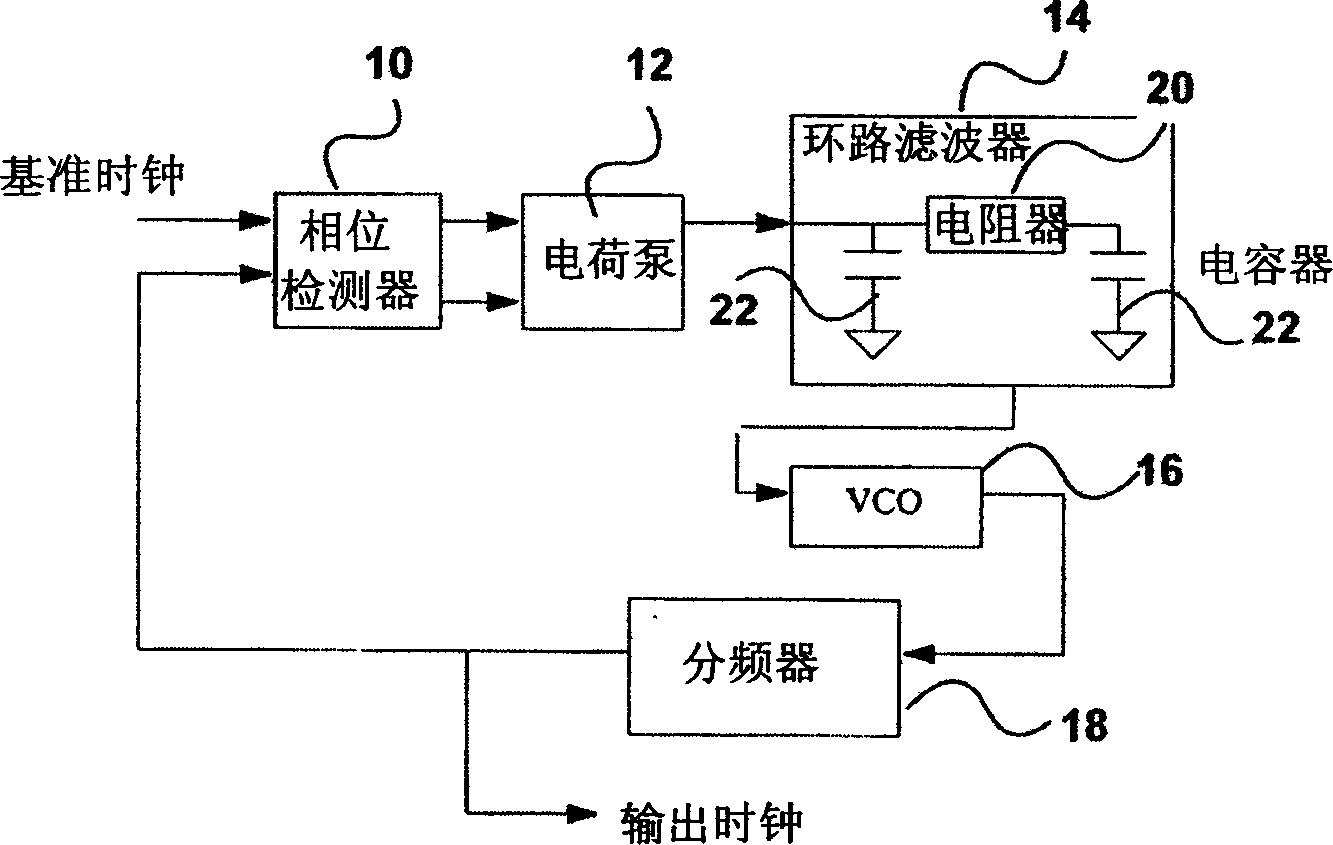
[0021] figure 1 is the block diagram of a common phase-locked loop. The phase-locked loop comprises: a phase detector 10 receiving a reference signal and a feedback signal at its input; a charge pump receiving the output of the phase detector 10, which converts the detected phase difference into During the varying source or sink current, a voltage controlled oscillator 16 whose output is fed back to the input of the phase detector 10 via a frequency divider 18 . Loop filter 14 includes resistor 20 and capacitor 22 .
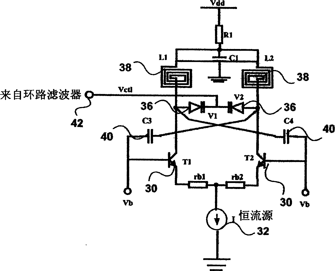
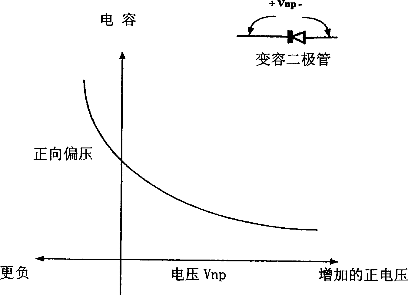
[0022] figure 2 A voltage controlled oscillator 16 is shown comprising: a pair of transistors 30, a constant current source 32, a resistor 34, a pair of varactor diodes 36 (variable capacitance capacitors), a pair of inductors 38, and a pair of capacitors 40. Input 42 receives control voltage V from loop filter 14 ctl . During operation, the control voltage V ctl Changing the capacitance of the varactor diode 36 in the LC circuit changes the output freque...
PUM
 Abstract
Description
Claims
Application Information