
Correction apparatus

A correction device and correction coefficient technology, which is applied to TVs, color TV parts, electrical components, etc., can solve problems such as inability to process in real time, inability to fully calibrate areas, and inability to quickly respond to dynamic changes in camera devices, etc.

Inactive Publication Date: 2004-11-03
CANON KK
View PDF0 Cites 9 Cited by
  • Summary
  • Abstract
  • Description
  • Claims
  • Application Information

AI Technical Summary

Problems solved by technology

[0016] However, in the above-mentioned conventional example, since the correction coefficient is calculated only under certain conditions such as capturing a standard white image, there is a problem that it cannot be processed in real time.
Therefore, there are cases where the inconsistency between regions cannot be sufficiently corrected for dynamic changes such as temperature changes or changes over time, or changes in the focus of the imaging optical system, etc.
[0017] In addition, it may not be able to respond quickly to dynamic changes such as hand shake of the camera, and may not be able to sufficiently correct the inconsistency between regions.

Method used


Image

  • Correction apparatus
  • Correction apparatus
  • Correction apparatus

Examples


Embodiment Construction

[0063] Hereinafter, an embodiment in which the correction of the present invention is applied to an imaging device will be described with reference to the drawings.

[0064] (First Embodiment)

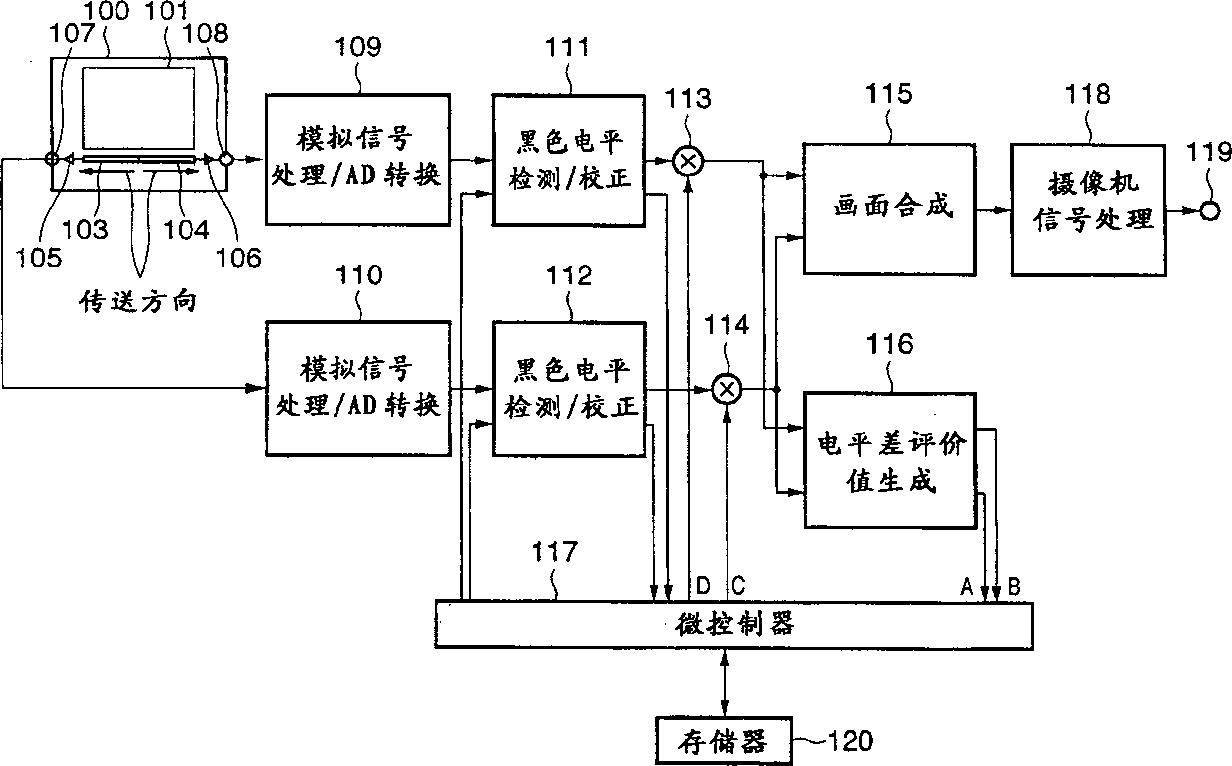
[0065] figure 1 It is a diagram schematically showing an embodiment in which the correction device of the present invention is applied to a single-board camera.

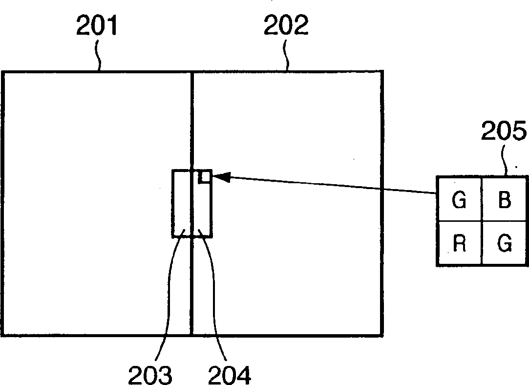
[0066] figure 1 Among them, 100 is a CCD area sensor that divides the imaging area into two areas, and each area has an output terminal. 101 is a photoelectric conversion part and a vertical transfer part, 103 and 104 are horizontal transfer parts, which are bordered by the center of the screen It is divided into two parts in the left and right direction.

[0067] 105 and 106 are output amplifiers for amplifying signal charges, and 107 and 108 are output terminals for image pickup signals. In addition, 109 and 110 are analog front ends for correlated double sampling and AD conversion. 111 and 112 are black level detection and...


PUM


Abstract

An object of this invention is to correct the non uniformity between a plurality of image sensing regions in real time and cope with even dynamic variations such as temperature variations or variations over time. To achieve this object, a correction apparatus includes a plurality of level adjustment devices which independently adjust the levels of a plurality of image sensing signals output from a plurality of output terminals, an output level detection device which detects the output levels of the plurality of level adjustment devices, and a correction coefficient determination device which determines a correction coefficient for reducing the level difference between the image sensing signals on the basis of the detection result of the output level detection device. The correction coefficient determination device determines the correction coefficient by excluding an object-dependent level difference component in which the level difference between the plurality of image sensing signals exceeds a predetermined level difference. The correction coefficient determination device supplies the determined correction coefficient to the level adjustment devices to perform adjustment so as to reduce the level difference between the image sensing signals.

Description

Technical field [0001] The present invention relates to a correction device, and more particularly, to a technology of a correction device that is preferably suitable for dividing an imaging surface into a plurality of regions for correcting a signal from a solid-state imaging element, the solid-state imaging element including an amplifier that amplifies the imaging signal of each region, and Connect to multiple image pickup signal output terminals output by the amplifier. Background technique [0002] In recent years, with the advancement of digital signal processing technology and semiconductor technology, a digital recording standard television system, such as the NTSC system and PAL system of moving image signals, has been proposed for civilian digital television standards. As its application, a digital video recording system has been developed. A digital video camera integrated with a playback device and a camera device. In this type of digital video camera, it has the chara...

Claims


Application Information

Patent Timeline
Patent Type & Authority Applications(China)
IPC IPC(8): H04N23/40
CPCH04N5/23248H04N5/3653H04N23/68H04N25/41H04N25/672
Inventor 服部雄一郎稻生和也
Owner CANON KK
Learn More