Slit double gap buncher and method for improved ion bunching in an ion implantation system

A technology of beam concentrator and ion beam, which is applied in the direction of deflecting/concentrating/focusing the beam current with electric/magnetic devices, discharge tubes, accelerators, etc., and can solve ion loss (such as not provided to the workpiece, long time, etc.) question

Inactive Publication Date: 2004-11-10
AXCELIS TECHNOLOGIES
View PDF1 Cites 3 Cited by
  • Summary
  • Abstract
  • Description
  • Claims
  • Application Information

AI Technical Summary

Problems solved by technology

In conventional systems, where approximately 80% of the ions generated by the ion source may be lost (eg not delivered to the workpiece), it takes much longer to perform the desired implant

Method used


Image

  • Slit double gap buncher and method for improved ion bunching in an ion implantation system
  • Slit double gap buncher and method for improved ion bunching in an ion implantation system
  • Slit double gap buncher and method for improved ion bunching in an ion implantation system

Examples


Embodiment Construction

[0020] The present invention will be described below with reference to the accompanying drawings, in which similar elements are marked with similar reference numerals. A dedicated ion buncher section is provided for bunching ions in the ion implantation system. The ion buncher section may be used in the linac upstream of the accelerating section to provide an ion beam or ion packet such that ion losses in the linac are reduced. The buncher section can operate at lower energy levels than the subsequent accelerator section and can also provide a drift region to facilitate ion bunching. The present invention also includes an asymmetric double-gap buncher section, and a slit buncher section to further improve ion implantation efficiency. Methods for accelerating ions in a linear accelerator of an ion implanter are also described below.

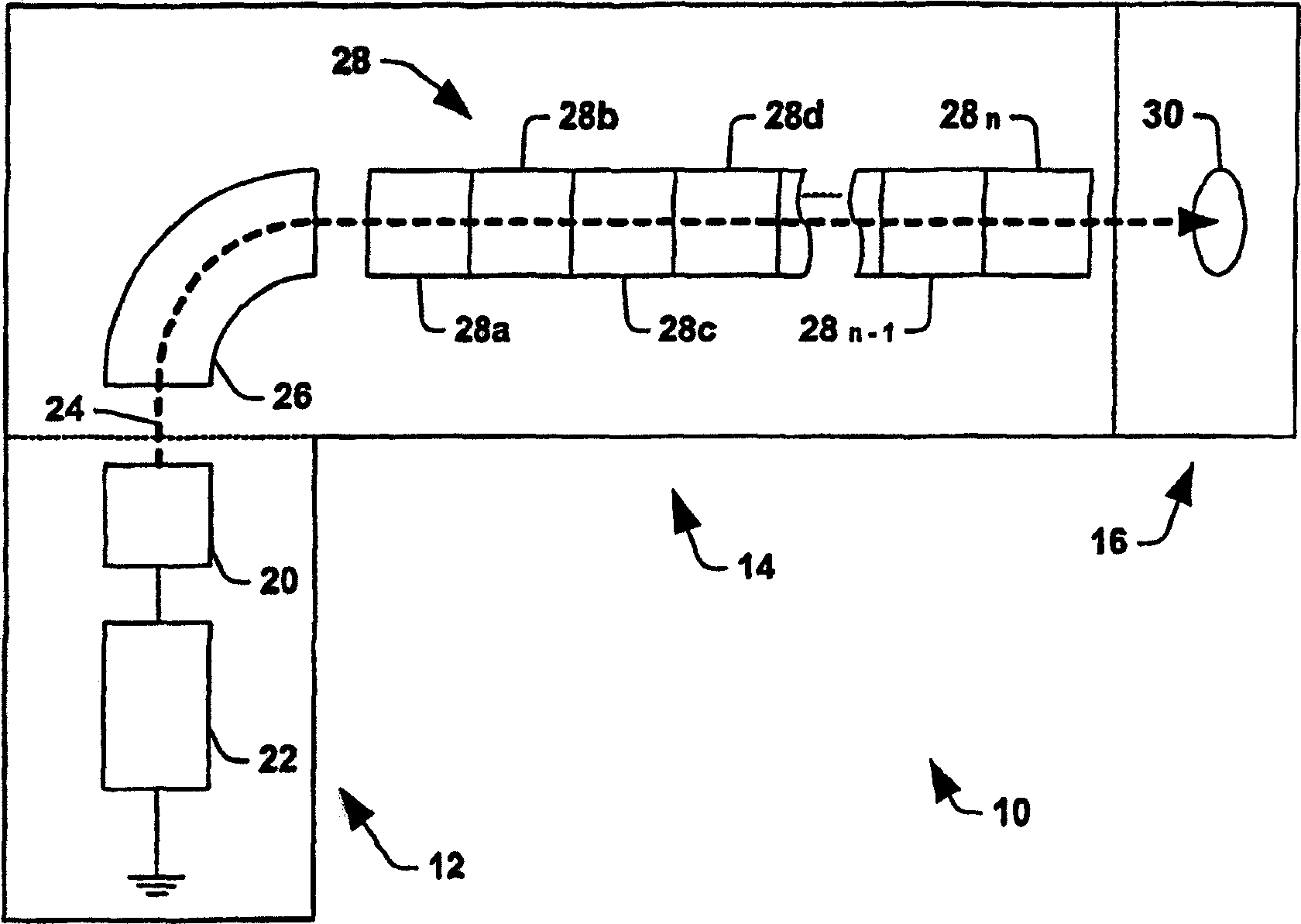
[0021] In order to provide context for the features of the present invention, a linear accelerator module (such as figure 1 The conventional i...


PUM


Abstract

An ion buncher stage for a linear accelerator system is disclosed for bunching ions in an ion implantation system. The ion buncher stage may be employed upstream of one or more linear accelerator stages such that the loss of ions in the linear accelerator system is reduced. The invention further includes an asymmetrical double gap buncher stage, as well as a slit buncher stage for further improvement of ion implantation efficiency. Also disclosed are methods for accelerating ions in an ion implanter linear accelerator.

Description

technical field [0001] The present invention mainly relates to an ion implantation system, and in particular, relates to an improved ion bunching method and equipment in the ion implantation system. Background technique [0002] In the manufacture of semiconductor devices, ion implantation is used to dope semiconductors with impurities. A high energy (HE) ion implanter is described in US Patent No. 4,667,111, which is assigned to the assignee of this patent and is incorporated herein by reference in its entirety. This high-energy ion implanter is used for deep implants in substrates to create, for example, inverted wells. For such deep implants, the implant energy is typically 1.5 MeV (megaelectron volts). Such injectors typically perform implants at energies of at least 300 keV to 700 keV, although lower energies are available. Some high energy ion implanters are capable of delivering ion beams with energy levels as high as 5 MeV. [0003] see figure 1 , shows a typica...

Claims


Application Information

Patent Timeline
Patent Type & Authority Applications(China)
IPC IPC(8): G21K1/08G21K5/04H01J37/147H01J37/317H05H7/18
CPCH01J2237/04737H05H7/18H01J2237/04924H01J37/3171
Inventor K·萨亚达特曼德W·迪韦吉利奥
Owner AXCELIS TECHNOLOGIES
Why Eureka
Try Eureka