Method and apparatus for monitoring grain output and flow rate of complete harvester

A technology of combine harvester and monitoring device, which is applied in the direction of harvester, measuring device, weighing, etc., and can solve problems such as difficult installation.

Active Publication Date: 2004-11-17
CHINESE ACAD OF AGRI MECHANIZATION SCI
View PDF0 Cites 31 Cited by
  • Summary
  • Abstract
  • Description
  • Claims
  • Application Information

AI Technical Summary

Problems solved by technology

However, this method is difficult to be directly installed on the existing combine harvester, and the installation problem is the biggest difficulty in the design of the flow sensor

Method used


Image

  • Method and apparatus for monitoring grain output and flow rate of complete harvester
  • Method and apparatus for monitoring grain output and flow rate of complete harvester
  • Method and apparatus for monitoring grain output and flow rate of complete harvester

Examples


Embodiment Construction

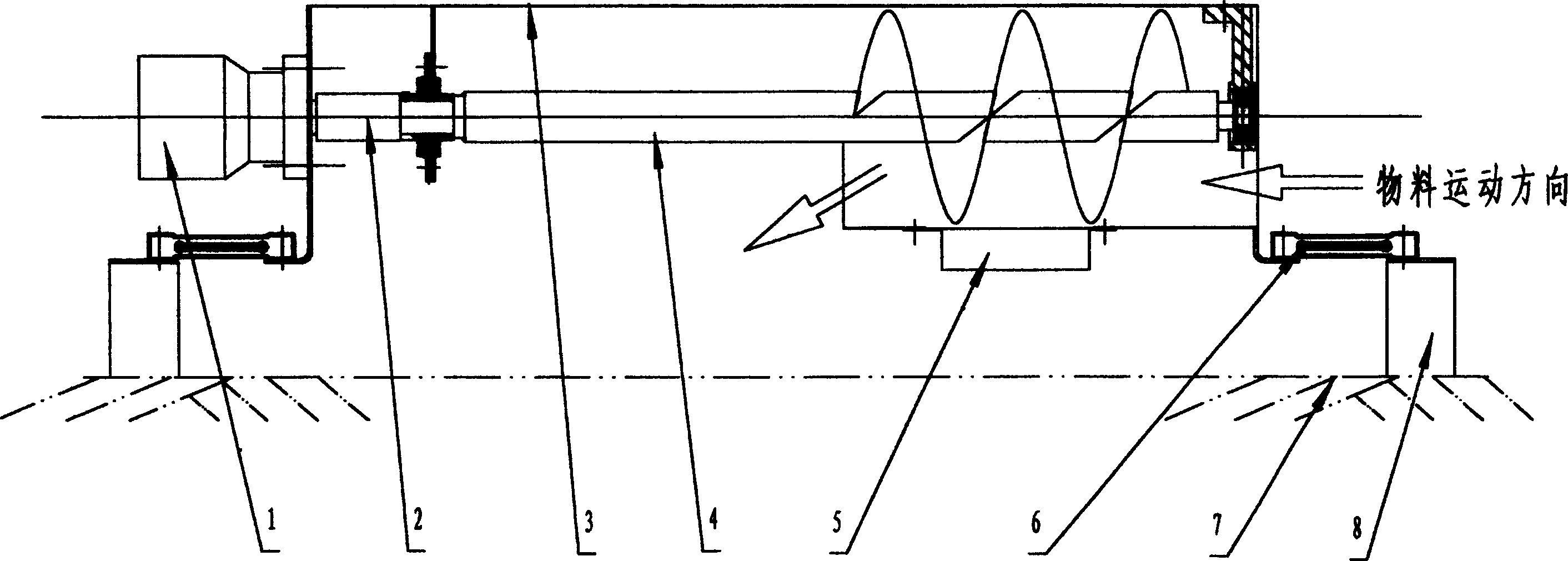
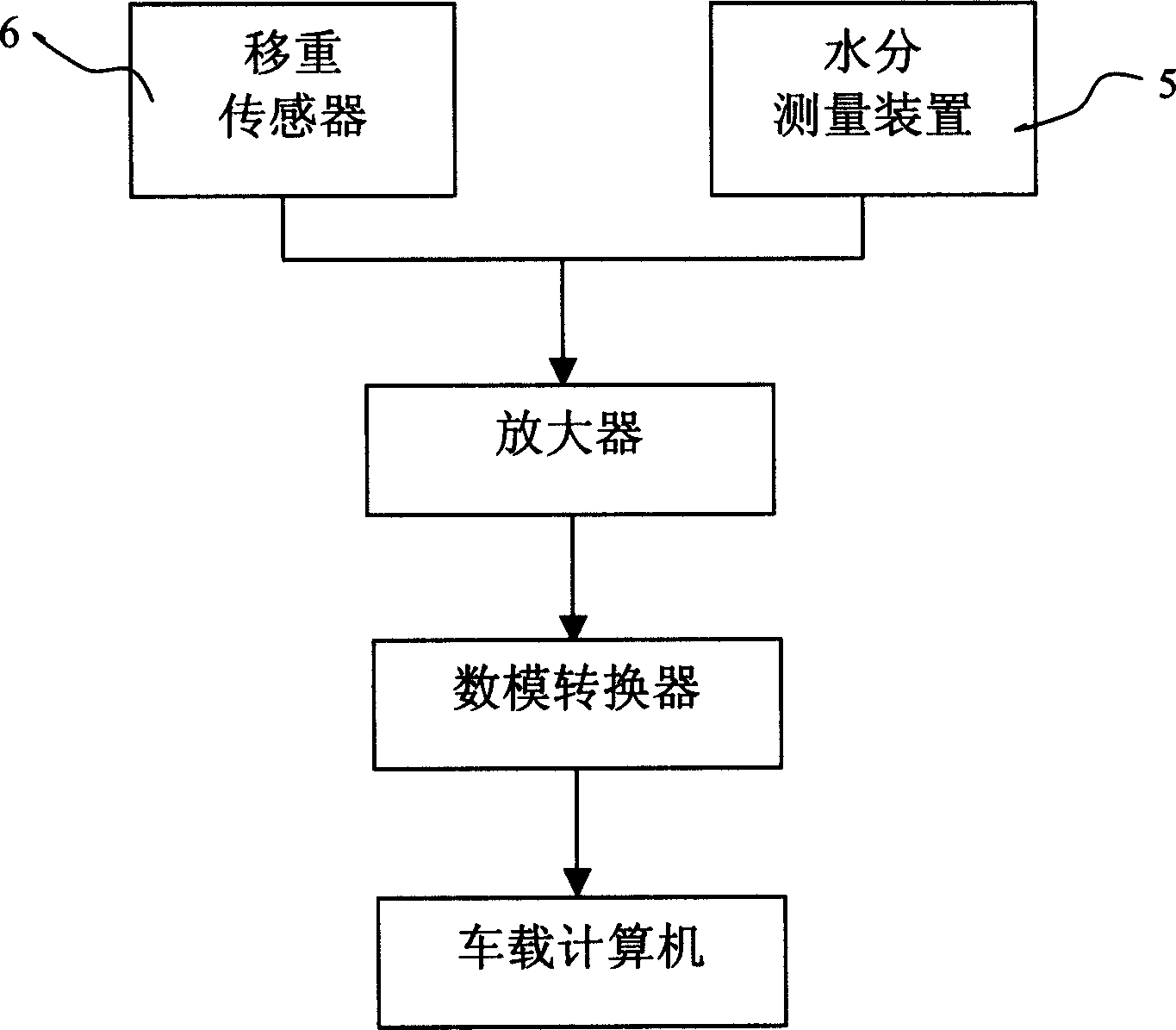
[0026] in figure 1 Among them, the output monitoring device of a combine harvester required by the present invention includes: a driving device 1, a coupling 2, a conveyor housing 3, a screw pusher, a moisture measuring device 5, a load cell 6, a frame 7, Damping platform 8. The driving device 1 is connected to the screw pusher 4 through the coupling 2 to drive the screw pusher 4. Under the action of the auger 4, the material to be measured is drawn between the auger 4 and the conveyor housing 3. figure 1 Movement in the horizontal direction as shown in. During the movement of the material, the moisture content of the material is measured by the moisture measuring device 5 installed on the lower side of the conveyor shell 3. The weighing sensor 6 installed between the conveyor housing 3 and the shock-absorbing platform 8 is responsible for measuring the gravity signal of the material and feeding the signal back to the on-board computer. The on-board computer integrates the measu...


PUM


Abstract

The invention discloses a grain flow monitoring process and apparatus for a combine-harvester, wherein the apparatus is mounted on the rack of the combine-harvester, comprising a driving device, a helical conveyer, a moisture measuring apparatus, a weighing sensing unit, a vehicle mounted signal processing circuit and a vehicle mounted computer, wherein the helical conveyer is provided with two weighing sensing devices at the two sides of the casing, the helical conveyer casing is connected with the rack through the sensing devices, and the moisture measuring apparatus is arranged on the bottom inside the helical conveyer.

Description

Technical field [0001] The invention relates to a method and device for monitoring grain output flow, in particular to a method and device for monitoring grain output flow of a combine harvester. Background technique [0002] As an important part of the grain flow monitoring of the combine harvester, the grain flow measurement method has many different measurement principles. [0003] One is the method of using impact / force sensing technology: by installing a sensor that measures the impact force at the exit of the grain lifter, the grain flow rate can be measured to obtain the grain flow rate information. At the exit of the grain lifter, the grains periodically hit the force plate along the guide plate device, and the force measurement signal is transmitted to the A / D converter through the amplifier, which is converted into a digital signal and stored in the computer memory. The accuracy of this measurement method is not only related to the weight of the grain, but also depends ...

Claims


Application Information

Patent Timeline
Patent Type & Authority Applications(China)
IPC IPC(8): A01D41/127G01G11/00G01N33/18
Inventor 张小超王志苑严伟
Owner CHINESE ACAD OF AGRI MECHANIZATION SCI
Why Eureka
Try Eureka