

Aeroengine materials hot end environment experimental simulation method and device
An aero-engine and environmental experiment technology, which is applied in the field of aero-engine material hot-end environmental experiment simulation and devices, can solve the problems of high simulation cost, high fuel consumption, and high cost, and achieve short simulation time, high simulation temperature, and environmental protection. The effect of all factors
Inactive Publication Date: 2004-11-17
NORTHWESTERN POLYTECHNICAL UNIV
View PDF0 Cites 37 Cited by
- Summary
- Abstract
- Description
- Claims
- Application Information
AI Technical Summary
Problems solved by technology
However, there are three problems in the assessment of components through test run or test flight: (1) The process of test run or test flight is complicated, involving a wide range of areas, and the cost is very expensive; (2) Because the influence of the complex real engine environment is not considered, the There is a great uncertainty in the actual life; (3) the damage mechanism cannot be determined after the abnormal failure of the component, and it is difficult to provide informa
Method used
View moreImage
Smart ImageViewing Examples

Examples
 PUM
| Property | Measurement | Unit |
|---|---|---|
| Granularity | aaaaa | aaaaa |
| Maximum operating temperature | aaaaa | aaaaa |
Abstract
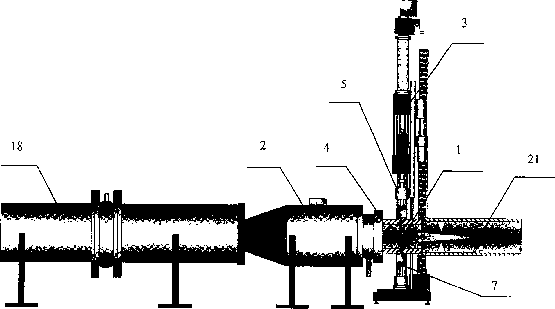
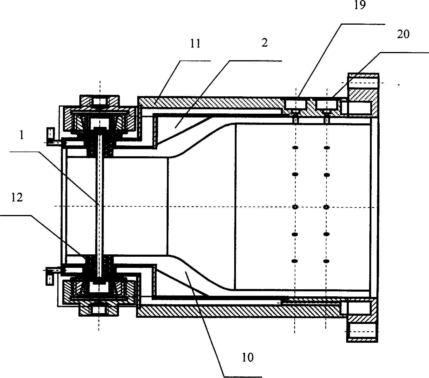
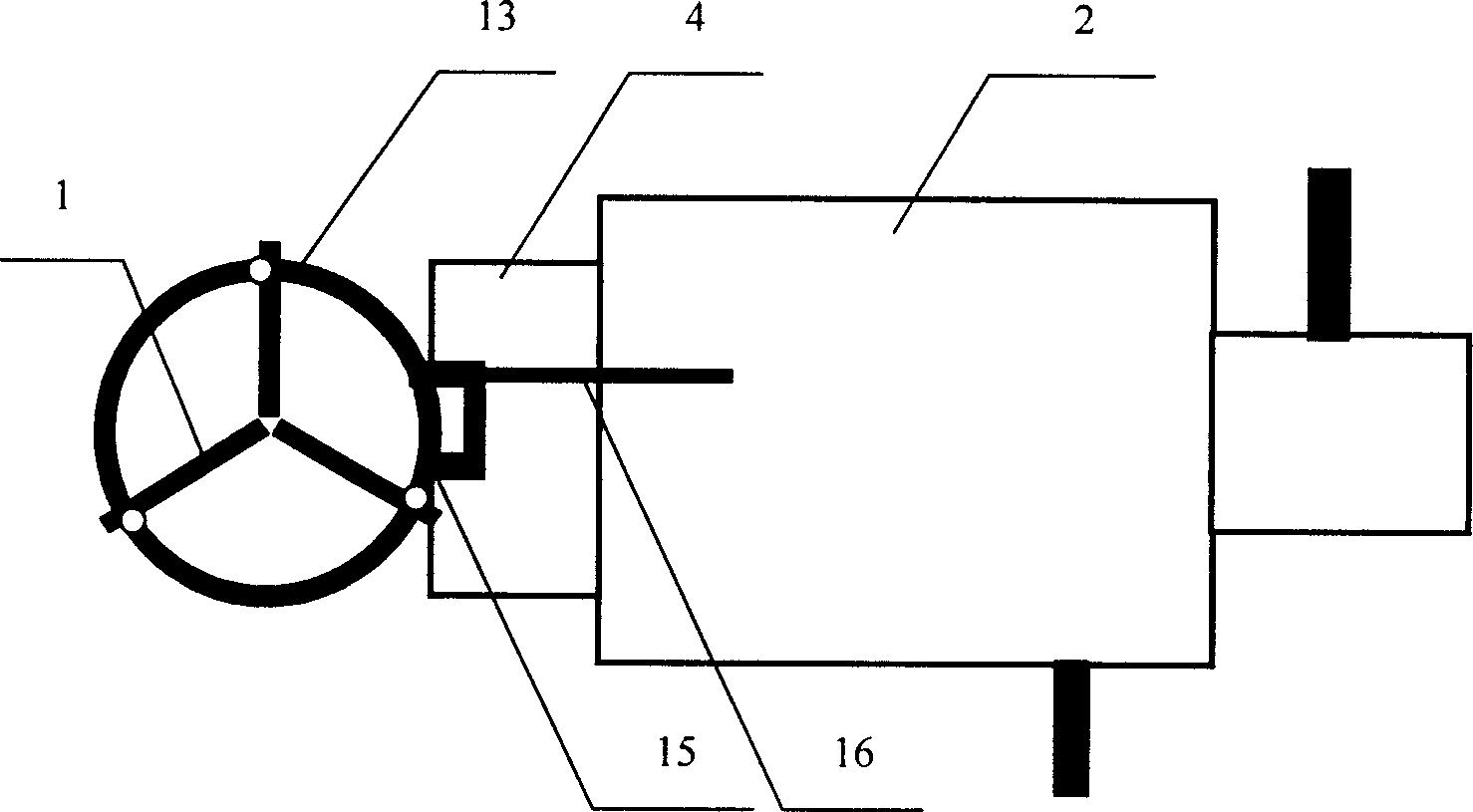
The invention discloses a hot end environment experimental-analogic method and device for a kind of aviation engine material. The invention carries on thermal shock simulation by using constant gas temperature to change the sample position, carries on accelerating simulation by using oxygen, water and salt water solution to change the gas composition. The invention combines the normal pressure subsonic velocity air tunnel and material performance testing machine, the invention uses the silicon nitride and silicon carbonate ceramic as the linings of the combustion chamber to upgrades the high temperature resisting level of the combustion chamber. The structure of sample bracket, rotary chain, and rotary handle can carry on hot shock simulation. There distributes with gas apertures and water apertures around the combustion chamber, it can upgrade the high oxygen partial pressure and the water partial pressure, it upgrades the melted salt partial pressure through salt dissolved in the water. The invention has a high simulating temperature, short time, and it is safe.
Description
technical field [0001] The invention relates to a simulation method and device for an aero-engine material hot-end environment experiment, in particular to using a subsonic subsonic high-temperature wind tunnel at atmospheric pressure combined with a material performance testing machine to carry out multi-factor coupling acceleration experiment simulation suitable for high-temperature gas environment conditions. It is mainly used for physical modeling of the environmental performance evolution of aerospace thermal structural materials such as superalloys and ceramic matrix composites, and can also be used for environmental performance testing of other thermal structural materials. Background technique [0002] At present, the known high-temperature wind tunnel is mainly used to simulate aero-engine components to determine the stress field and temperature field of the components, and provide a basis for the design and verification of the components. Although the theoretical l...
Claims
Login to View More Application Information
Patent Timeline
 IPC IPC(8): G01M9/02G01M15/00
Inventor成来飞张立同徐永东栾新刚刘小瀛
OwnerNORTHWESTERN POLYTECHNICAL UNIV