Optical mechanism improvement for optical mouse

An optical mouse, optical mechanism technology, applied in computer parts, mechanical mode conversion, input/output process of data processing, etc., can solve problems such as the reduction of light source brightness

Inactive Publication Date: 2004-11-24
SUNPLUS TECH CO LTD
View PDF0 Cites 8 Cited by
  • Summary
  • Abstract
  • Description
  • Claims
  • Application Information

AI Technical Summary

Problems solved by technology

In this way, the brightness contrast of the light source received by the light sensor 53 will be reduced, making it di

Method used


Image

  • Optical mechanism improvement for optical mouse
  • Optical mechanism improvement for optical mouse
  • Optical mechanism improvement for optical mouse

Examples


Embodiment Construction

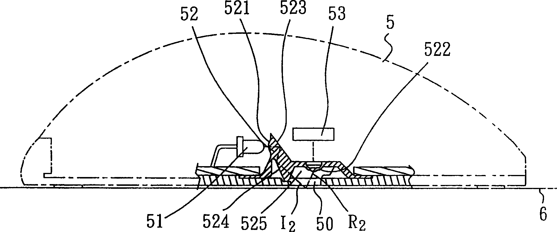
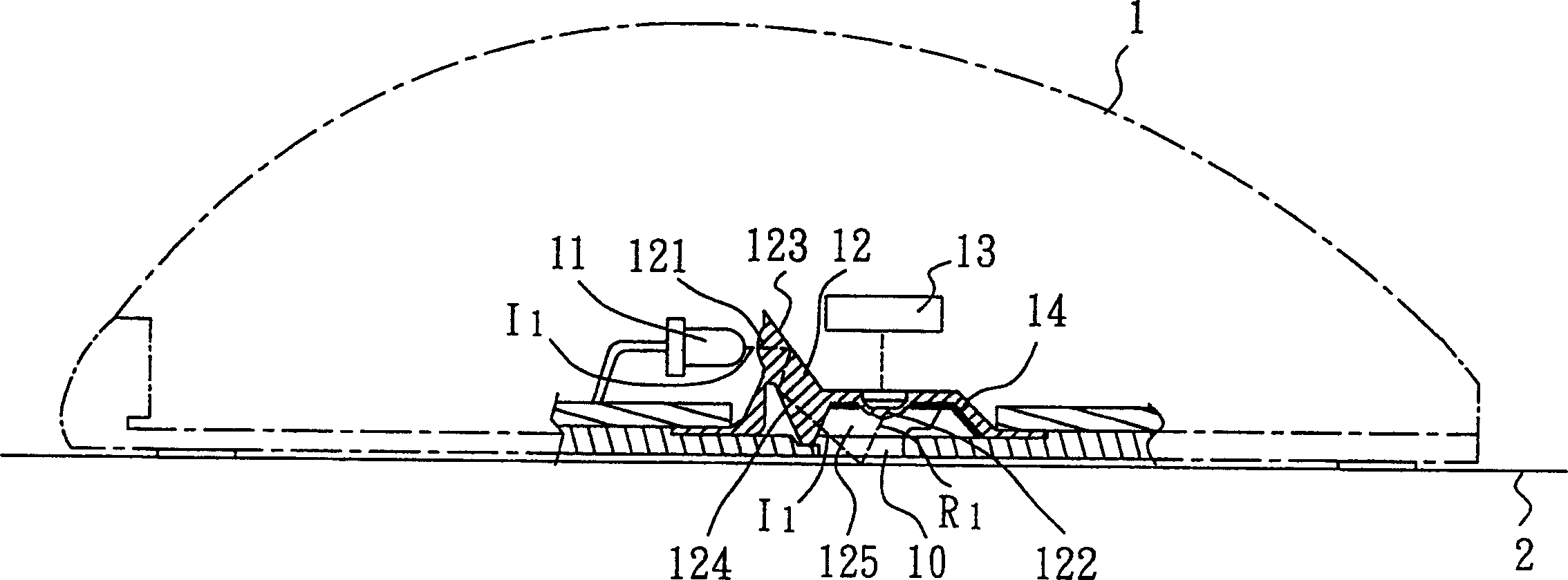
[0015] Please also refer to Figure 3 to Figure 5 Implementation status of preferred embodiments of the present invention. in, image 3 An opening 10 is provided at the bottom of the display optical mouse 1, and a group of optical mechanisms are provided in the inner space. The optical mechanism of this embodiment includes a light source device 11, a light guide device 12, a light sensor 13, and a light-absorbing layer 14. Among them, the light source device 11 is preferably a light-emitting diode crystal grain (LED Die), or can be other equivalent illuminants; the light-absorbing layer 14 is preferably a black paint, which is directly coated / adhered on the surface to absorb the light source Of course, the light-absorbing layer 14 can also be formed by performing surface treatment on the surface to absorb the light source.

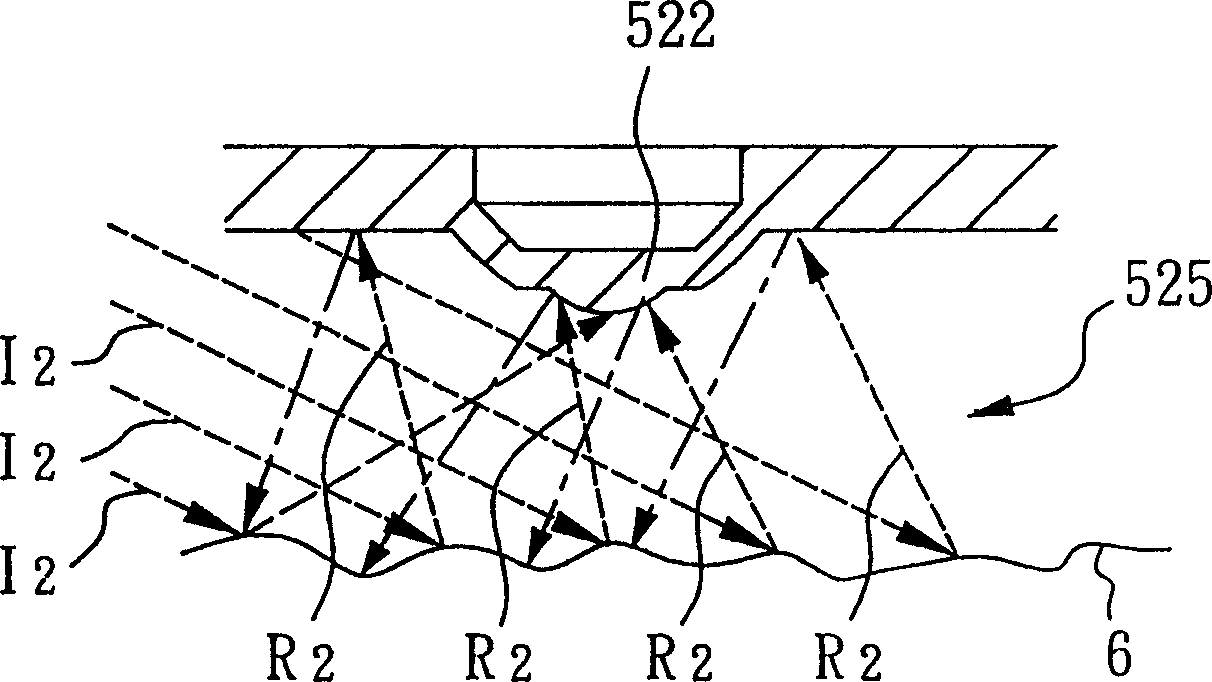
[0016] Such as image 3 As shown, the incident light source I projected by the light source device 11 of this embodiment 1 is parallel to the reflect...


PUM


Abstract

The improve optical mechanism for optical mouse is assembled inside optical mouse, and has one black paint layer painted to the side surface of the light sensor or one other light absorbing layer formed through surface treatment of the said surface to absorb reflected light, which is not projected to the light sensor. The light sensor has increased contrast and raised image judging capacity.

Description

technical field [0001] The invention relates to an improvement of a mouse mechanism, especially an improvement of an optical mechanism suitable for an optical mouse. Background technique [0002] In the existing optical mouse technical field, the principle is mainly to judge the action of the optical mouse by judging the unevenness or micro-concavity formed on the surface of the application plane (such as a desktop or a mouse pad). [0003] see figure 1 and figure 2 The existing optical mechanism assembled in the inner space of the optical mouse and its phase diagram show that the optical mechanism in the existing optical mouse 5 mainly includes a light source device 51 , a light guide device 52 , and a light sensor 53 . The light source device 51 can project an incident light source I 2 to the first lens 521 of the light guide device 52 , and reflected by the first prism 523 and the second prism 524 to pass through the opening 50 at the bottom of the optical mouse 5 and...

Claims


Application Information

Patent Timeline
IPC IPC(8): G06F3/0354
Inventor 王庆彬曾立文
Owner SUNPLUS TECH CO LTD
Why Eureka
Try Eureka