Fan control apparatus

A fan control and control circuit technology, applied in the control system, temperature control using electric mode, DC motor speed/torque control, etc., can solve the problem of damage to the cooling device

Inactive Publication Date: 2004-12-01
GIGA BYTE TECH CO LTD
View PDF2 Cites 9 Cited by
  • Summary
  • Abstract
  • Description
  • Claims
  • Application Information

AI Technical Summary

Problems solved by technology

However, if its control circuit 13 is damaged or does not work normally, it will seriously affect the normal operation of its entire power supply system or power supply line. In other words, the entire power supply system or power supply line will stop working. The motor ...

Method used


Image

  • Fan control apparatus
  • Fan control apparatus
  • Fan control apparatus

Examples


Embodiment Construction

[0024] In order to better understand the purpose, features and effects of the present invention, the present invention will be described in detail through the following embodiments and accompanying drawings, as follows.

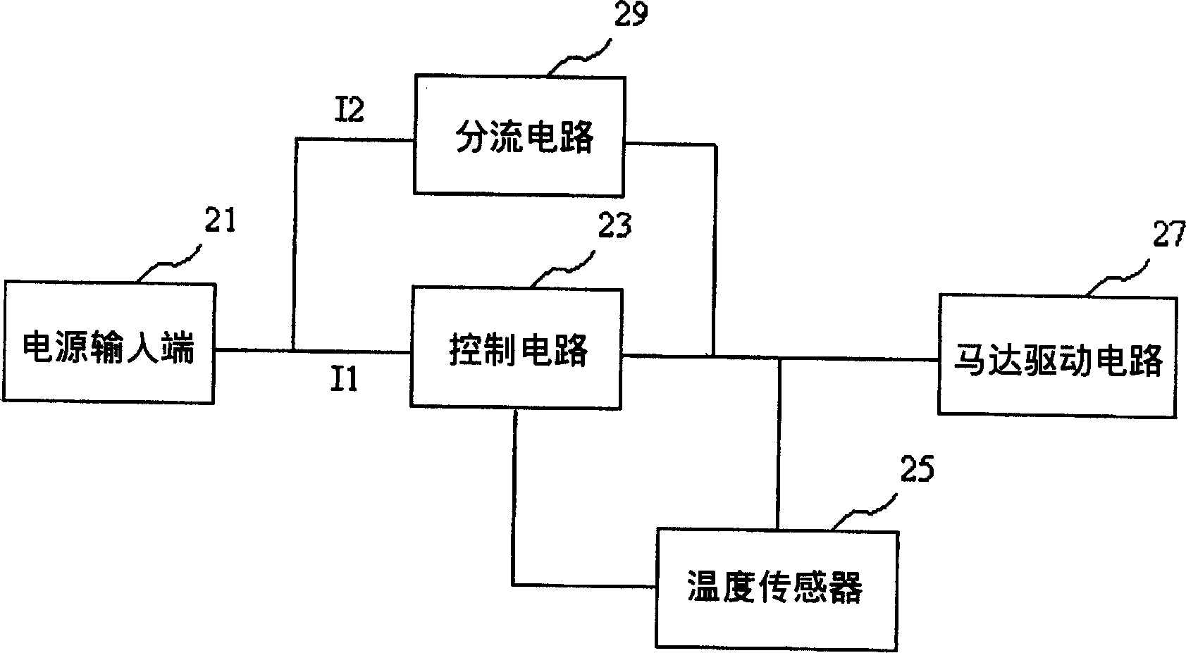
[0025] First, see figure 2 , is a schematic circuit diagram of a preferred embodiment of the present invention; as shown in the figure, the main structure of the present invention includes a control circuit 23, the input end of the control circuit 23 can be connected to a power supply or power input end 21, and its The output end can be connected to a motor driving circuit 27 directly or through a power control circuit (not shown). Also, one end of the control circuit 23 can be connected with a temperature sensor 25, through which the temperature sensor 25 can detect the working environment temperature of the heat dissipation device such as the central processing unit or chipset, and notify the control circuit 23 according to this data to provide how much vo...


PUM


Abstract

The invented device ensures power supply for heat radiating fan normally. A divided circuit is connected between input end of power source and circuit of driving motor so that the divided circuit is connected to control circuit in parallel. When in normal operation of the control circuit, both of the control circuit and the divided circuit together is as power supply lines for the heat radiating fan. When in abnormal operation caused by disabled control circuit, the divided circuit becomes as power supply line solely. Thus, power supply for heat radiating fan is ensured.

Description

technical field [0001] The invention relates to a fan control device, in particular to a fan control device capable of ensuring normal power supply of a cooling fan. Background technique [0002] In the information society, the size of the chip or processor used in the computer system has become smaller and smaller, but its computing speed has been relatively doubled, so the accompanying working temperature has also increased significantly. In order to avoid affecting the central processing unit due to excessive working temperature For the computing efficiency and normal operation of the cooling device such as chips or chips, it is necessary to use a heat sink or cooling fan on the central processing unit or chip to eliminate its high temperature and ensure the safety of the cooling device. [0003] And general cooling fans all need a power supply system and power supply line to maintain the power supply of its normal operation, such as Taiwan Patent Publication No. 460093, ...

Claims


Application Information

Patent Timeline
IPC IPC(8): G05D23/19
Inventor 刘登杰
Owner GIGA BYTE TECH CO LTD
Why Eureka
Try Eureka