Continuous microlens array amplifying displaying antifogery method

A technology of microlens array and magnified display, which is applied in the direction of lens, decorative art, and patterns characterized by light projection effects, which can solve the problems of inconvenient observation, unrecognizable graphics and fonts, etc., and achieve convenient portability, unique display effect, low cost effect

Inactive Publication Date: 2004-12-08
INST OF OPTICS & ELECTRONICS - CHINESE ACAD OF SCI
View PDF0 Cites 52 Cited by
  • Summary
  • Abstract
  • Description
  • Claims
  • Application Information

AI Technical Summary

Problems solved by technology

Graphics and typefaces cannot be read without the aid of a magnifying glass or microscope
However, the anti-counterfeiting method of magnifying

Method used


Image

  • Continuous microlens array amplifying displaying antifogery method
  • Continuous microlens array amplifying displaying antifogery method
  • Continuous microlens array amplifying displaying antifogery method

Examples


Embodiment 1

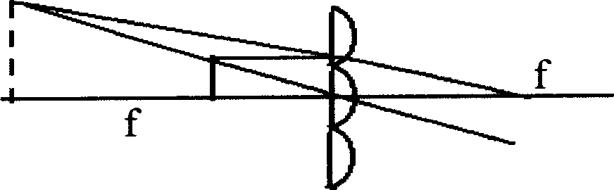
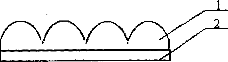
[0032] Example 1, such as figure 1 , Figure 4 As shown, firstly, the micrographics or microstructures are made, which is completed by using a relatively simple filming method. The diameter of each sub-graph is designed to be 200 μm, and the figure is crescent-shaped. The output is generated by the filming machine and formed on organic materials, such as plastic films. Above; secondly, use the method of microfabrication to manufacture microlens arrays with diameters of 200 μm and shapes that match the micrographics. The continuous microlens arrays are formed on the surface of gelatin photoresist materials by moving masks. The method can be dry or wet etching or a combination of dry and wet methods, and the pattern is transferred to the surface of the organic plastic by copying. The microphotograph of the microlens is as follows: Figure 5 Shown; Finally, combine the two with the combination glue method, such as figure 2 As shown, it is combined into a micro-graphic and a mi...

Embodiment 2

[0033] Embodiment 2, making and displaying μ characters.

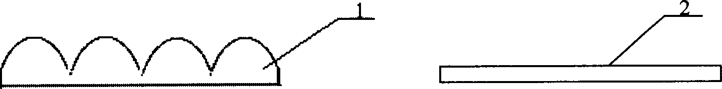
[0034] First, make micro-graphics or micro-structures, use the laser direct writing method to make a mask to obtain micro-graphics or micro-structures, the designed sub-graphics have an aperture of 100 μm, and the graphics are μ characters, which are directly produced on the surface of the chromium layer on the glass substrate, such as Figure 7 shown. The continuous microlens array is molded by grayscale mask method, and formed on the surface of optical materials (such as fused silica, K9) by direct etching, such as Figure 8 Shown is a 3D profile of the microlens array. Using separate methods, such as image 3 shown. The display results obtained during observation are as follows Figure 9 shown.

Embodiment 3

[0035] Embodiment 3, the display of various graphics.

[0036] First, laser printing is used to obtain fine graphics, the sub-graphics have a diameter of 150 μm, and the graphics are square and circular, such as Figure 10 Shown; Make the microlens array again, use the grayscale mask method to form on the photoresist material, and then press the microlens on the plastic surface, and the two are combined by film pressure.


PUM

PropertyMeasurementUnit
Caliberaaaaaaaaaa
Caliberaaaaaaaaaa

Abstract

A continuous microlens array magnifying display method for antiforge purpose is disclosed. The printing, laser printing, fine processing and microcarving are used to make the micrographics. The fine processing is used to make the microlens array with continuous surface. The diameter of each microlens is matched with that of each micrographics. After they are combined in different modes, a 3D magnifying display effect with single graphics-single color or multiple graphicses-multiple colors is obtained, which can be used for antiforge purpose.

Description

technical field [0001] The invention relates to an anti-counterfeiting method for enlarging and displaying continuous microlens arrays, which belongs to micro-optical display technology. Background technique [0002] In recent years, anti-counterfeiting technology has developed rapidly, mainly based on laser holograms. However, this technology has been semi-disclosed, and the anti-counterfeiting function has been challenged. There are also various methods such as code anti-counterfeiting, which are inconvenient and complicated to realize. [0003] For this reason, people have proposed to adopt enlarging display anti-counterfeiting method, the principle of this anti-counterfeiting method is: under normal lighting conditions, the limit resolution angle of human eyes is 1 '. Under the condition of a photopic distance of 250mm, the limit resolution of the human eye is 0.072mm. Generally speaking, in order not to fatigue the eyes, the viewing angle of the human eye is about 4'...

Claims


Application Information

Patent Timeline
IPC IPC(8): B42D25/30G02B3/08G03F7/00
Inventor 邓启凌杜春雷周崇喜
Owner INST OF OPTICS & ELECTRONICS - CHINESE ACAD OF SCI
Why Eureka
Try Eureka