Special-process glass bottle and producing method thereof
A manufacturing method and technology of glass bottles, applied in glass manufacturing equipment, blown glass, manufacturing tools, etc., can solve the problems that can only be made by hand and cannot be produced, and achieve the effect of ornamental and clear shape
- Summary
- Abstract
- Description
- Claims
- Application Information
AI Technical Summary
Problems solved by technology
Method used
Image

Examples
example 1
[0023] figure 2 The setting conditions for Example 1 shown are as follows:
[0024] Weight 227.0g
[0025] Mold volume 113.6cc = (glass volume + punch volume + extension volume)
[0026] Glass volume 90.8cc
[0027] Punch volume 7.26cc
[0028] Extended volume 15.1cc
[0029] Elongation ratio 13.3% = (extension volume ÷ mold volume)
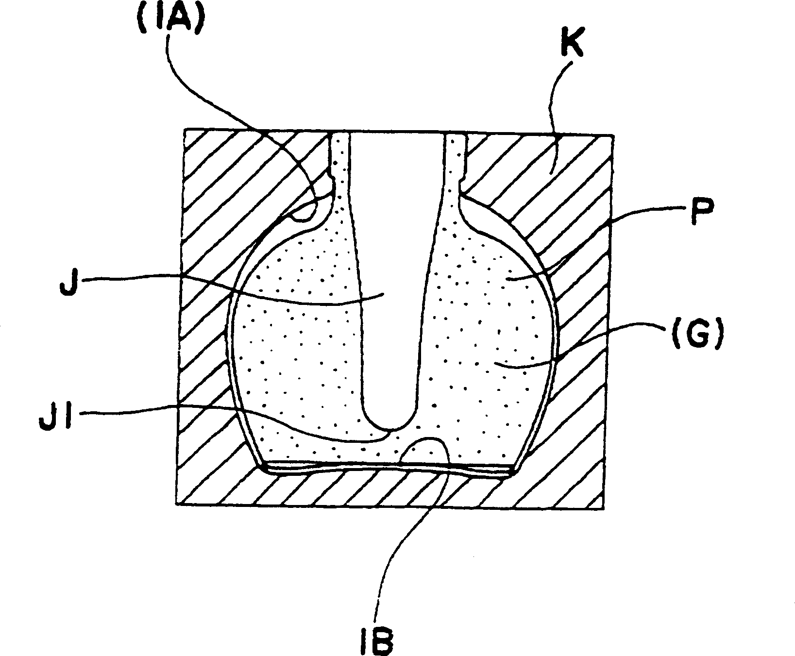
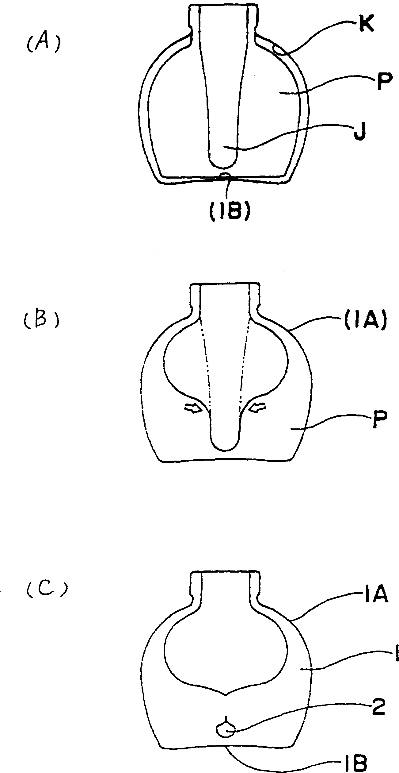
[0030] The distance from the top of the punch JI to the bottom of the bottle IB is set at 4mm.
[0031] Under this setting condition, the formation process of the raindrop-shaped bubble 2 is as follows: image 3 shown. image 3 Middle (A) indicates that the punch J rises to punch the gob G to form the blank P. image 3 The middle (B) shows the inside of the preform P after blowing with blown air. More than half of the extended volume of the blank P is set at the shoulder IA of the bottle I. When the air is being blown, the inner capacity of the shoulder IA increases, and the glass at the shoulder IA flows to the bottom of the blank P. ...
example 2
[0033] Such as Figure 4 The setting conditions of Example 2 shown are as follows, and the air bubbles 2 were not sufficiently formed in this example.
[0034] Weight 195.0g
[0035] Mold volume 113.26cc = (glass volume + punch volume + extension volume)
[0036] Glass volume 80.0cc
[0037] Punch volume 7.26cc
[0038] Extension volume 26.0cc
[0039] Elongation ratio 22.9% = (extension volume ÷ mold volume)
[0040] The distance from the top of the punch JI to the bottom of the bottle IB is set at 5 mm.
[0041] Compared with Example 1, the elongation ratio of the preform P is much higher in this setting condition, and the distance from the top of the punch JI to the bottle bottom IB is also 1 mm longer than that of Example 1. Such as Figure 4 As shown in (B), after punch J top J1 punch gob G, the space left at the top of the punch is obviously smaller than that of Example 1. Such as Figure 4 As shown in middle (C), the bottle 1 is formed after blowing air, and af...
example 3
[0043] Such as Figure 5 The setting conditions of Example 3 shown are as follows, and bubbles could not be formed in this example.
[0044] Weight 196.8g
[0045] Mold volume 113.22cc = (glass volume + punch volume + extension volume)
[0046] Glass volume 80.7cc
[0047] Punch volume 6.52cc
[0048] Extension volume 26.0cc
[0049] Elongation ratio 22.9% = (extension volume ÷ mold volume)
[0050] The distance from the top of the punch J1 to the bottom of the bottle IB is set at 6mm.
[0051] Compared with Example 1, the elongation ratio of the preform P is much higher in this setting condition, and the distance from the top of the punch JI to the bottle bottom IB is also 2mm longer than that of Example 1. Such as Figure 5 As shown in (B), after punching the gob G with the top JI of the punch J, the space left at the top of the punch J is significantly reduced compared with Example 1. Such as Figure 5 As shown in middle (C), bottle 1 is formed after blowing air, a...
PUM
 Abstract
Description
Claims
Application Information
 - R&D
- Intellectual Property
- Life Sciences
- Materials
- Tech Scout
- Unparalleled Data Quality
- Higher Quality Content
- 60% Fewer Hallucinations
Browse by: Latest US Patents, China's latest patents, Technical Efficacy Thesaurus, Application Domain, Technology Topic, Popular Technical Reports.
© 2025 PatSnap. All rights reserved.Legal|Privacy policy|Modern Slavery Act Transparency Statement|Sitemap|About US| Contact US: help@patsnap.com