A camera control apparatus and method

A technology for controlling devices and cameras, which can be used in image communication, television, instruments, etc., and can solve problems such as operator disorientation, limited number of memory, additional charges, etc.

Inactive Publication Date: 2004-12-08
尼尔・J・史蒂文森 +1
View PDF0 Cites 119 Cited by
  • Summary
  • Abstract
  • Description
  • Claims
  • Application Information

AI Technical Summary

Problems solved by technology

[0004] However, both of the above two types of systems have obvious deficiencies
Simultaneous zooming and panning or tilting shots are either not possible or cause disorientation for the operator
Moreover, the number of preset positions that can be preset is limited by the capacity of the memory and the additional cost caused by setting multiple preset positions for the camera

Method used


Image

  • A camera control apparatus and method
  • A camera control apparatus and method
  • A camera control apparatus and method

Examples


Embodiment Construction

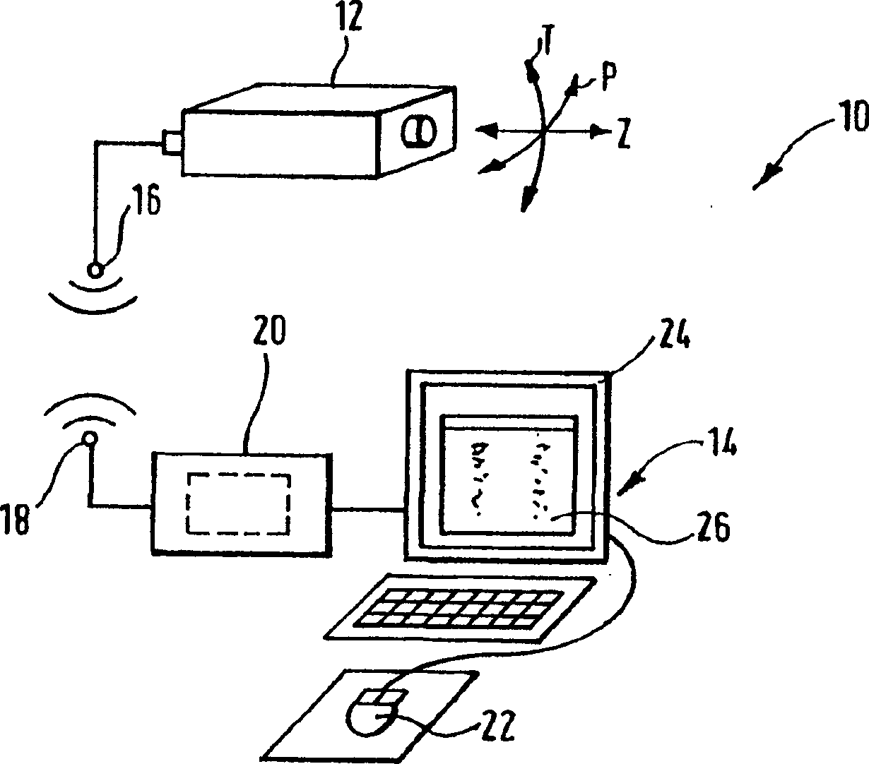
[0061] exist figure 1 In , the camera control device is generally denoted by 10 . The device comprises a camera 12, such as a closed circuit television camera. The camera 12 is configured to be able to rotate around a vertical axis to pan the camera, and to be able to rotate around a horizontal axis to tilt the camera. At the same time, the video camera is provided with a zoom mechanism so as to enlarge the image seen by the video camera. The pitch function of video camera 12, pan function and zoom function are in figure 1 is schematically shown with arrows P (pan), T (tilt) and z (zoom). The camera 12 is driven in the pan direction and the tilt direction by means of respective stepping motors (not shown).

[0062] The camera 12 is indirectly and electrically connected to a control unit 14 . This indirect electrical connection can be made by means of cables. or, as in figure 1 As shown, this connection can also be provided by means of a conventional telephone or mobi...


PUM


Abstract

A camera control apparats (10) comprises a control device for controlling the zoom, pan and tilt conditions of a camera. Data relating to the positioning of the camera in pan, tilt and zoom is transmitted to the control means and the control means converts the data into a value in a co-ordinate system, for example (3D) polar co-ordinates. The camera may be controlled and directed by pointing a pointer to an area in the image displayed whereby in response to selection of a point on a display the control means pans and / or tilts the camera so that the image viewed by the camera is centred substantially on the point selected. Still further, an area of the screen can be selected, for example by tracking and dropping a box using a mouse pointer on a computer screen and the control means is arranged to pan and tilt the camera so the image is centred on the centre of the selected area and zoomed so that the selected area becomes substantially the entire image viewed by the camera. In a further aspect a multiple camera control apparatus is provided in which a plurality of cameras may be controlled using the aforesaid control apparatus and the multiple camera control apparatus includes data relating to the location of the cameras with reference to the site plan so that multiple cameras can be co-ordinated to provide better image data, blind spot illumination and 'hand over' functionality. Still further a security apparatus is provided in which a camera views an image and the security apparatus includes image processing means and data relating to the site viewed by the camera so as to determine the location and size of an object viewed.

Description

technical field [0001] The present invention relates to a camera control device and method, in particular but not limited to a device and method for remotely controlling a closed circuit camera. Background technique [0002] Existing camera remote control systems are generally referred to as "telemetry control" systems. Usually, it just provides a simple remote control function, enabling the camera to be panned or tilted along an axis, and then adjusted to the desired zoom level. Such control can be achieved by means of a set of arrow keys controlling panning and / or tilting of the camera as well as controlling the zoom level. Thus, if the controller presses the "right" arrow key, the camera pans right during the key press. However, these systems do not provide a feedback function. In other words, the position of the camera or the level of zoom cannot be determined remotely. [0003] Some camera robotic devices, such as mechanized zoom lenses or pan / tilt heads, do provide...

Claims


Application Information

Patent Timeline
Patent Type & Authority Applications(China)
IPC IPC(8): H04N7/18
CPCG08B13/19608G08B13/19689H04N5/232G08B13/19641H04N7/181H04N7/185H04N23/661H04N23/631H04N23/695
Inventor 尼尔·J·史蒂文森乔纳森·R·R·马丁
Owner 尼尔・J・史蒂文森
Why Eureka
Try Eureka