An electro-acoustic transducer with two diaphragms

A technology of sound converters and converters, applied in the direction of transducer housings/cabinets/brackets, sensors, hearing aids, etc., can solve the problems of cumbersome design, distortion, and speakers that are not suitable for small designs, and achieve high efficiency.

Inactive Publication Date: 2004-12-08
桑尼昂克尔克公司
View PDF2 Cites 17 Cited by
  • Summary
  • Abstract
  • Description
  • Claims
  • Application Information

AI Technical Summary

Problems solved by technology

The design has a number of disadvantages, since parameters such as size and weight are not important due to the technology involved in the upper two-way loudspeaker, the design is very cumbersome and bulky
So the loudspeaker of JP07 131893A is not suitable for small desi

Method used


Image

  • An electro-acoustic transducer with two diaphragms
  • An electro-acoustic transducer with two diaphragms
  • An electro-acoustic transducer with two diaphragms

Examples


Embodiment Construction

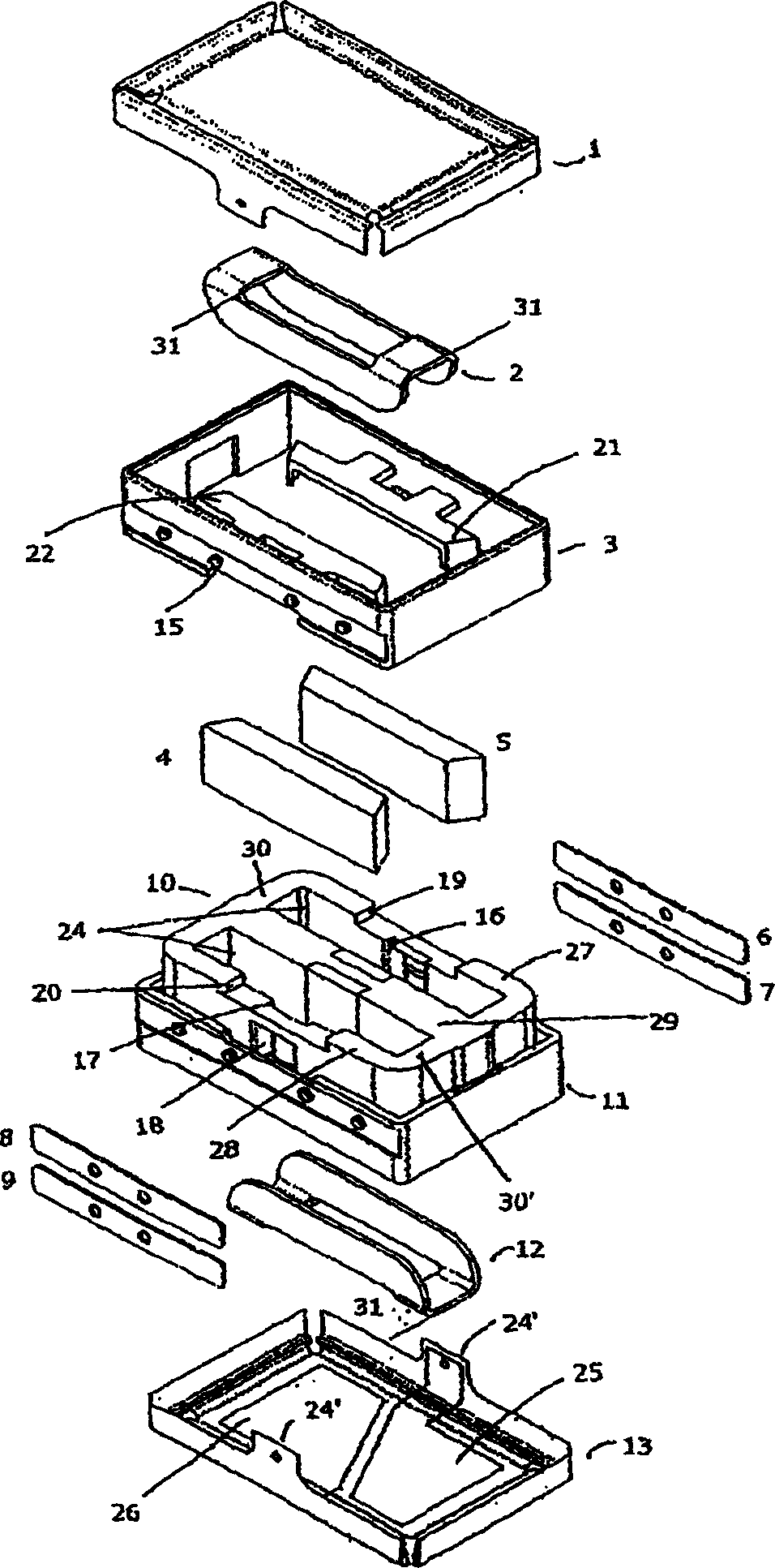
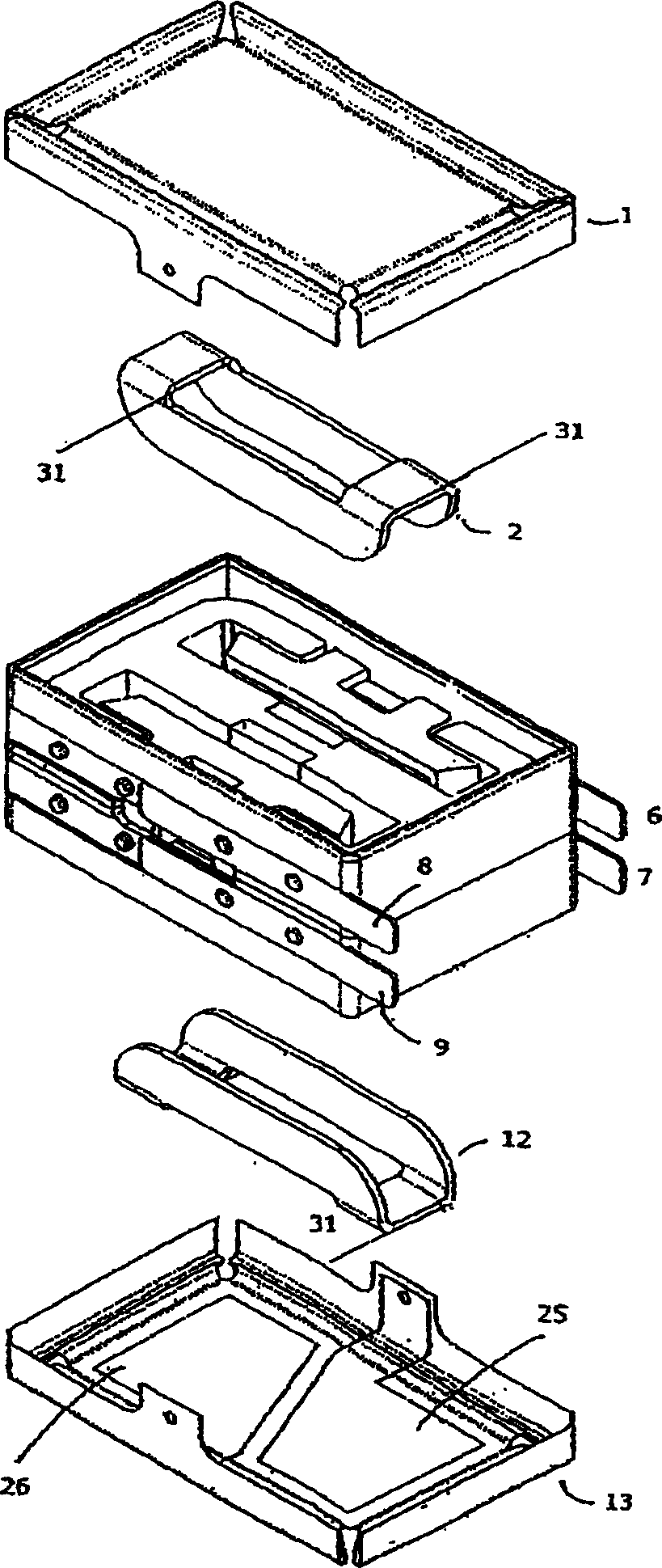
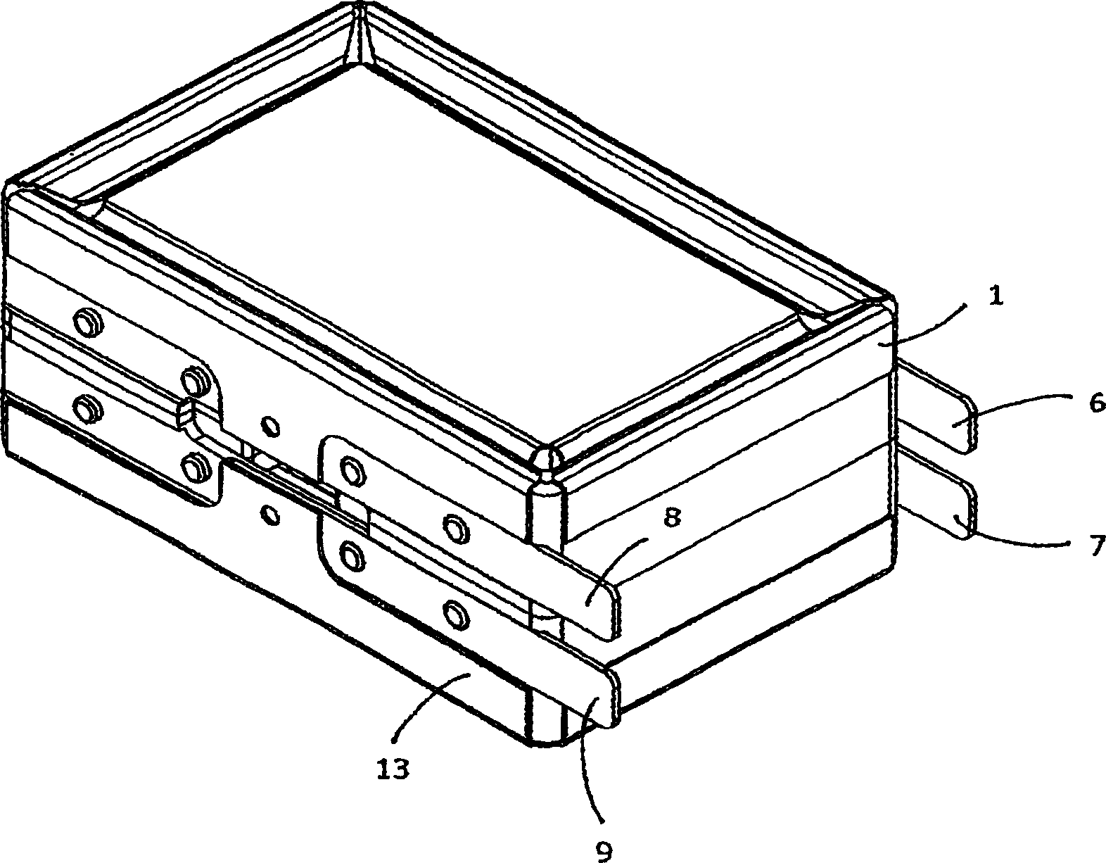
[0050] Figure 1-3 An electromotive power converter is shown and has the main components: magnetic circuit 10, first coil 2, second coil 12, first diaphragm 1, second diaphragm 13 and four connections 6-9.

[0051] Such as figure 1 As shown, the electromotive power converter according to the invention comprises two diaphragms 1, 13 and two coils 2, 12, and has a common magnetic circuit. The two diaphragms mentioned above are driven by two modes of operation, either same polarity or opposite polarity. If the two diaphragms are driven in the same direction in response to an input electrical signal, the transducer is driven by a so-called vibration mode. Vibrate mode induces maximum vibration, but no sound output. If the two diaphragms are driven in opposite directions, there will be maximum sound output and the transducer is free to vibrate. Terminals 6, 8 are in electrical contact with coil 2 and terminals 7, 9 are in electrical contact with coil 12. The contact between th...


PUM


Abstract

The present invention relates to an electro-acoustic transducer suitable for applications within mobile communication equipment and hearing aids. The transducer comprises two diaphragms positioned on opposite sides of a magnetic circuit having two magnetic gaps. When used as a microphone the transducer is substantially insensitive to vibrations, and when used as a speaker the transducer generates only very low vibration levels. The magnetic circuit has a number of advantages compared to conventional transducers with circular magnetic. The transducer can be made lightweight and with very compact dimensions compared to conventional designs. In a preferred embodiment the diaphragms are rectangular. The transducer may additionally be used as a vibration generator for silent alarm signals.

Description

technical field [0001] The present invention relates to an electroacoustic transducer, in particular to an electrodynamic transducer with double diaphragms, each of which can carry a coil of electric wire that can move in a magnetic field. Background technique [0002] Electroacoustic transducers, especially electrodynamic transducers, are widely used in communication equipment, such as wired telephones, mobile telephones or cellular telephones, and in hearing aids that require a small-sized structure. Whether the converter is used as a microphone or a speaker (microphone), it converts a sound signal into an electrical signal, and vice versa. For microphones and speakers used in small devices, it is critical that such converters be vibration-resistant to avoid unwanted noise or feedback problems. [0003] If the microphone and speaker are in close proximity to each other, especially in hearing aids, a feedback loop can be created due to the vibrations produced by the speake...

Claims


Application Information

Patent Timeline
IPC IPC(8): H04R1/00H04R1/02H04R7/02H04R7/04H04R9/00H04R9/02H04R9/06H04R9/08H04R25/00H04R31/00
CPCH04R9/046H04R25/00H04R9/025H04R9/063H04R31/006H04R2499/11
Inventor 莱夫・约翰森吉格・A・范霍尔特恩
Owner 桑尼昂克尔克公司
Why Eureka
Try Eureka