Planar display apparatus

A display device, a planar technology, applied to lighting devices, static indicators, instruments, etc., can solve the problems of insignificant decrease in brightness and non-existence of brightness

Inactive Publication Date: 2004-12-22
SANYO ELECTRIC CO LTD
View PDF0 Cites 11 Cited by
  • Summary
  • Abstract
  • Description
  • Claims
  • Application Information

AI Technical Summary

Problems solved by technology

[0012] However, for example if Figure 9 As shown, in the organic EL display (1), when white is displayed in the central area B of the screen, and a certain intermediate color is displayed around it, compared with the left and right areas displaying intermediate colors, the driving lines indicated by dotted lines ( The brightness of the upper and l

Method used


Image

  • Planar display apparatus
  • Planar display apparatus
  • Planar display apparatus

Examples


Embodiment Construction

[0041] best practice

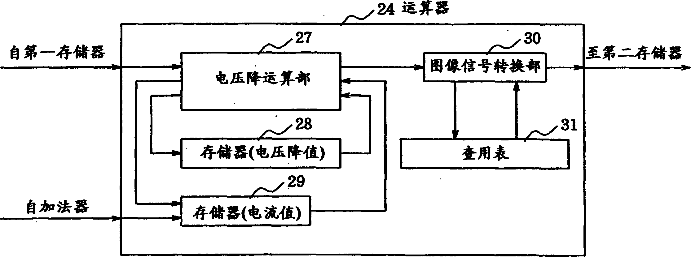
[0042] Hereinafter, embodiments of the active matrix organic EL display of the present invention will be specifically described with reference to the drawings. Such as figure 1 As shown, the organic EL display device according to the present invention includes an active matrix type organic EL display (2) and a power supply circuit (3) for supplying driving power to the organic EL display (2). The input signal of the organic EL display (2), after figure 1 The shown correction circuit C performs a correction process described later, and then supplies it to the organic EL display (2).

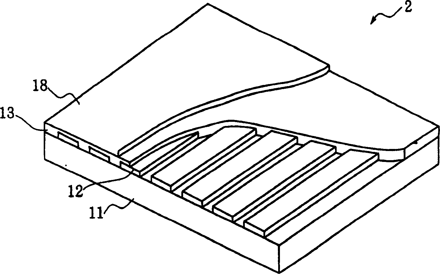
[0043] The organic EL display (2) can adopt such as image 3 As shown, the anode (12) is formed into a strip shape extending in the vertical direction of the screen, and the cathode (18) is formed into a sheet shape, or as Figure 4 As shown, the anode (12) is formed in the form of a strip extending in the horizontal direction of the screen, and the cathode (18) is for...


PUM


Abstract

The invention provides a flat display device which comprises for pixels arranged along drive lines a voltage drop calculator 27 for calculating a voltage drop occurring in accordance with the position of each pixel, and a video signal converter 30 and a lookup table 31 for correcting the input signal to be supplied to the pixel in accordance with the magnitude of the calculated voltage drop, whereby crosstalk due to the voltage drop is prevented.

Description

technical field [0001] The present invention relates to a flat type display device such as an organic electroluminescent display device or an inorganic electroluminescent display device. Background technique [0002] In recent years, the development of self-luminous flat-panel displays such as organic electroluminescent displays (hereinafter referred to as organic EL displays) and inorganic electroluminescent displays (hereinafter referred to as inorganic EL displays) has been progressing, and for example Research on the use of organic EL displays in mobile phones. [0003] Such as Figure 6 and Figure 7 As shown, the organic EL display uses a glass substrate (11) as a base, and an organic hole transport layer (15) and an organic electron transport layer (16) are arranged on both sides of the organic light-emitting layer (14) to form an organic layer (13). An anode (12) and a cathode (17) are arranged on both sides of the organic layer (13), and a predetermined voltage is...

Claims


Application Information

Patent Timeline
IPC IPC(8): G09G3/20G09G3/32
CPCG09G2300/0842H01L27/3281G09G3/20G09G3/3233G09G2320/0285G09G2320/0223H10K59/17
Inventor 井上益孝村田治彦森幸夫山下敦弘木下茂雄
Owner SANYO ELECTRIC CO LTD
Why Eureka
Try Eureka