
Optical fiber simulated Raman scattering effect based optical neuron and establishment method thereof

A stimulated Raman scattering and neuron technology, applied in the field of optical communication, can solve problems such as low fan-in and fan-out coefficients, dispersion, and technical difficulties in electronic interconnection of electronic devices

Inactive Publication Date: 2013-06-26
XIAN UNIV OF POSTS & TELECOMM
View PDF2 Cites 7 Cited by
  • Summary
  • Abstract
  • Description
  • Claims
  • Application Information

AI Technical Summary

Problems solved by technology

Since the electronic leads cannot short-circuit and cross each other, coupling will occur when the leads are close to each other, dispersion and delay will occur when the high-speed electric pulse propagates on the leads, and the fan-in and fan-out coefficients of electronic devices are low, making high-density electronic interaction Even with great technical difficulties

Method used


Image

  • Optical fiber simulated Raman scattering effect based optical neuron and establishment method thereof
  • Optical fiber simulated Raman scattering effect based optical neuron and establishment method thereof
  • Optical fiber simulated Raman scattering effect based optical neuron and establishment method thereof

Examples


Embodiment 1

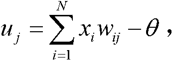
[0056] Such as figure 1 As shown, the optical neuron based on the stimulated Raman scattering effect in the optical fiber of the present invention includes (N-1) external optical transmitters 1 for emitting (N-1) signal lights, for emitting The first local optical transmitter 2 of the first local signal light, the second local transmitter 3 for emitting the second local signal light and the subtractor 4 for subtracting the electric signal, and for (N -1) A multiplexer 5 for coupling the (N-1) signal lights emitted by the external optical transmitter 1 and the first local signal light emitted by the first local optical transmitter 2, the first to (N-1) The output ends of each of the external optical transmitters 1 are respectively connected to the first to (N-1) input ends of the multiplexer 5 through (N-1) first optical fibers 6, and the first local optical transmitter The output end of the machine 2 is connected to the Nth input end of the multiplexer 5 through the second op...

Embodiment 2

[0061] The difference between this embodiment and Embodiment 1 is that the weights of the optical neurons can be positive or negative, and among the center wavelengths of (N-1) external optical transmitters 1, there are The central wavelengths of each are arranged in descending order and are all smaller than the central wavelength of the first local optical transmitter 2 in addition The central wavelengths of each are arranged in descending order and are all greater than the central wavelength of the first local optical transmitter 2 Wherein, N is an even number. The central wavelength of the first local optical transmitter 2 Satisfy the frequency shift calculation formula Δ υ 1 ‾ = ( 1 / λ ‾ 1 ) - ( 1 ...


PUM

PropertyMeasurementUnit
Dispersion valueaaaaaaaaaa
Nonlinear coefficientaaaaaaaaaa

Abstract

The invention discloses an optical fiber simulated Raman scattering effect based optical neuron and an establishment method thereof. The optical neuron comprises external optical transmitters, a first local optical transmitter, a second local optical transmitter, a subtracter, a combiner, a third optical fiber, an optical filter, a first optical-electrical converter, a second optical-electrical converter and a laser diode, wherein the third optical fiber performs power cumulative summing operation by non-linear effect of simulated Raman scattering. The method includes: selecting the external optical transmitters and the first local optical transmitter, performing coupling output by the combiner, selecting the third optical fiber for power cumulative summing operation, selecting the optical filter, selecting the first optical-electrical converter, selecting the second local optical transmitter and the second optical-electrical converter, constructing the subtracter, and selecting the laser diode for converting electrical signals to optical signals. The optical neuron is novel and reasonable in design, convenient to implement, low in cost, power consumption and noise, rapid in information processing, high in expandability and practicality, good is using effect and convenient to popularize and use.

Description

technical field [0001] The invention relates to the technical field of optical communication, in particular to an optical neuron based on the stimulated Raman scattering effect in an optical fiber and a method for establishing the same. Background technique [0002] By simulating the hierarchical structure of the human brain, people construct a new computing system - artificial neural network. It is a type of artificial intelligence system that simulates the organizational structure, processing methods and system functions of the biological nervous system. Since the artificial neural network is a parallel distributed processor with a large number of connections, it can solve the practical problems of pattern recognition, perception and decision-making in complex environments by learning, compared with the mechanical execution of the program programmed in advance by humans. Computer, which has a better ability to solve problems and adapt to the environment. [0003] Due to ...

Claims


Application Information

Patent Timeline
IPC IPC(8): H04B10/2537H04B10/50H04B10/25
Inventor 巩稼民左旭赵云冷斌袁心易李栋方健巩明辉
Owner XIAN UNIV OF POSTS & TELECOMM
Learn More