
Strong force propulsion plant of continuous tube

A propulsion device and coiled tubing technology, applied in directional drilling, drilling with liquid/gas jets, etc., can solve the problems of difficulty in completing near-horizontal deep drilling construction, small contact area, small propulsion force, etc., and achieve improved propulsion. force, increase the propulsion friction surface, increase the effect of friction

Inactive Publication Date: 2004-12-29
TAIYUAN UNIV OF TECH
View PDF0 Cites 6 Cited by
  • Summary
  • Abstract
  • Description
  • Claims
  • Application Information

AI Technical Summary

Problems solved by technology

Due to the small contact area between the two opposing rolling friction wheels and the steel pipe, the friction force is small, and the propulsion force is small. Therefore, it is difficult for the propulsion device of the "water jet continuous propulsion directional drilling rig" to complete the near-horizontal deep drilling (greater than 200 meters). drilling construction

Method used


Image

  • Strong force propulsion plant of continuous tube
  • Strong force propulsion plant of continuous tube

Examples


Embodiment Construction

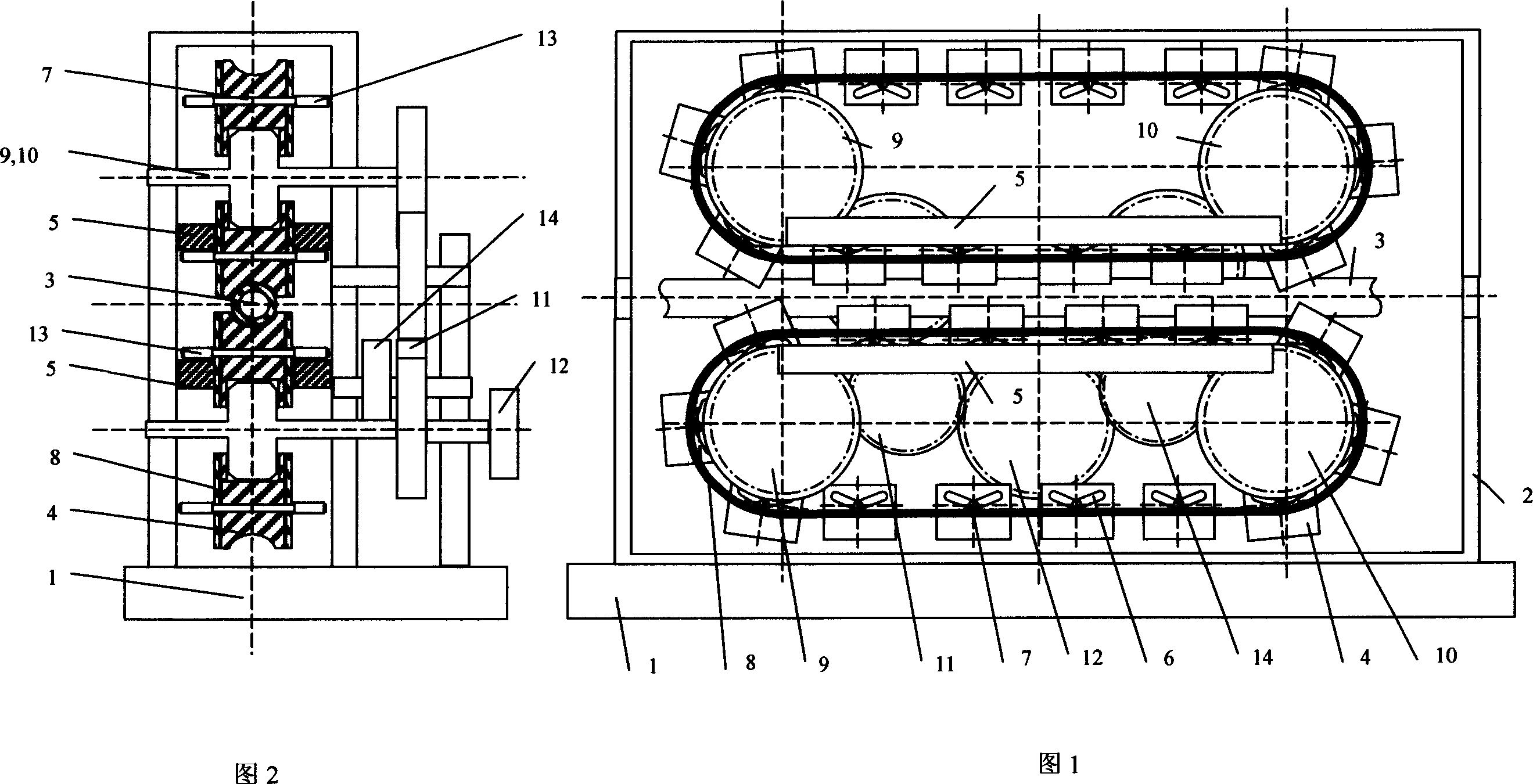
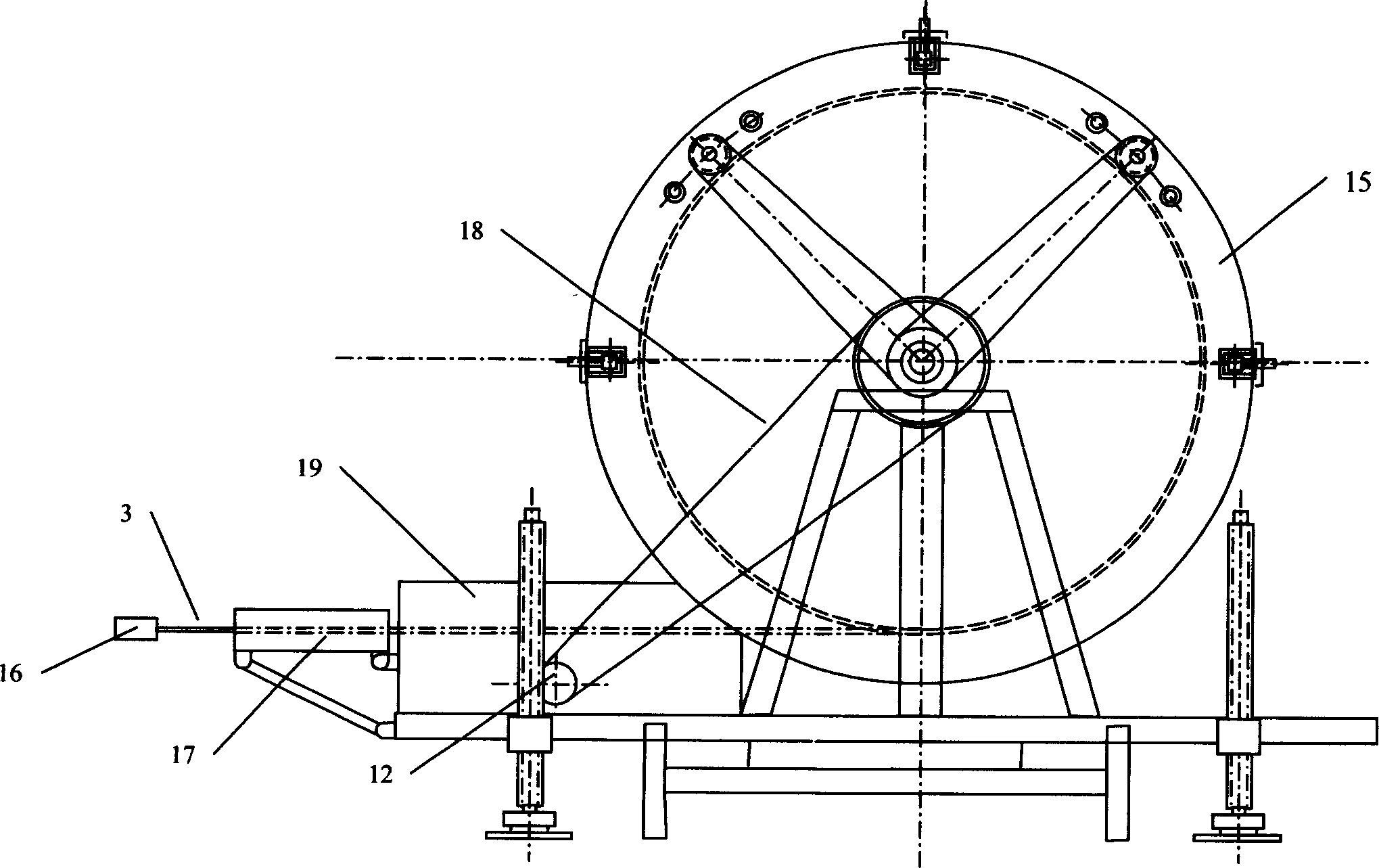
[0018] As shown in Figures 1 and 2, a powerful propulsion device for coiled tubing includes countermoving friction members arranged symmetrically up and down on the continuous pipe 3, and the friction members are a pair of closed On the transmission chain 8, evenly distributed and fixed friction blocks 4, each friction block 4 is connected with the transmission chain 8 through a shaft pin 7, and each friction block 4 is provided with an oblique track 6 of the shaft pin 7, in the continuous tube 3 The two limit rails 5 fixed up and down symmetrically are parallel to the continuous tube 3, and the rollers 13 installed at both ends of the shaft pin roll on the limit rails, and each transmission chain 8 is driven by the forward drive wheel 9 or the reverse drive wheel 10 , the main driving wheel 12 connected with the drilling rig drives the forward driving wheel 9 through the forward driving reversing wheel 11; or the main driving wheel 12 drives the reverse driving wheel 10 throug...


PUM


Abstract

The powerful control tube driving apparatus is suitable for driving various tubes inside deep hole in mining and geotechnical engineering. The present invention sets fixed friction blocks symmetrically to the transmission chain, and the friction blocks are connected to the transmission chain via shaft pin, are provided with inclined shaft pin rail. The two limiting rails symmetrically over and below the continuous tube are parallel to the continuous tube and made to contact with the roller of the shaft pin, and each transmission chain is driven with one pair of driving wheels. Compared with available technology, the present invention can produce much great continuous driving force to meet the requirement of drilling horizontal drilling over 200 m.

Description

Technical field: [0001] The invention belongs to the field of machinery, and can be applied to various pipelines in deep holes in mining projects and various geotechnical projects, and can also be used for laying urban underground pipelines and the like. Background technique: [0002] At present, in many fields such as mining engineering and geotechnical engineering, large-depth drilling is often required to achieve various engineering purposes. For example, underground coal mine drilling gas drainage, oil and gas field drilling (drilling) mineral drainage, and large-depth geological drilling. In addition, there are also laying operations such as urban underground pipelines. When the borehole (drilling) is not completely vertical, during the drilling process, when the friction force between the pipeline and the wall of the borehole is relatively large, a large push or drag force must be provided to the pipeline. For ultra-deep horizontal drilling or special construction te...

Claims


Application Information

Patent Timeline
Patent Type & Authority Applications(China)
IPC IPC(8): E21B7/04E21B7/18
Inventor 赵阳升常宗旭冯增朝王成寿杨栋康军赵建忠
Owner TAIYUAN UNIV OF TECH
Learn More