
Panel display and its backlight module

A flat-panel display and backlight module technology, applied to static indicators, light guides, optics, etc., can solve problems such as prolonging cleaning time

Inactive Publication Date: 2005-01-05
AU OPTRONICS CORP
View PDF0 Cites 9 Cited by
  • Summary
  • Abstract
  • Description
  • Claims
  • Application Information

AI Technical Summary

Problems solved by technology

Extends the time spent cleaning due to the need for reassembly

Method used


Image

  • Panel display and its backlight module
  • Panel display and its backlight module
  • Panel display and its backlight module

Examples


Embodiment Construction

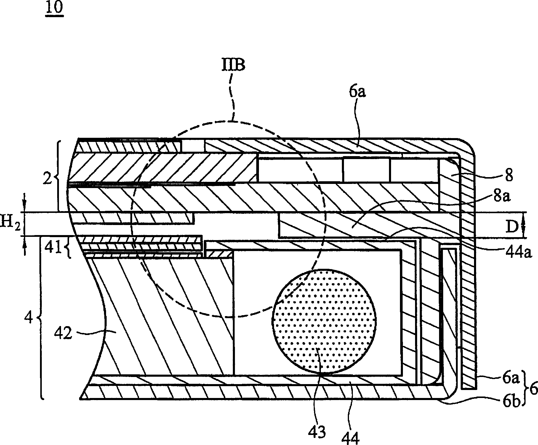
[0024] Figure 2A It is a schematic cross-sectional view of the liquid crystal display of the present invention. The liquid crystal display 10 includes a casing 6 , a plastic frame 8 , a panel 2 and a backlight module 4 . The casing 6 can be made of metal, and is composed of an upper casing 6a and a lower casing 6b, which surround the entire liquid crystal display 10, so as to reduce electromagnetic wave noise and enhance the overall structural strength.

[0025] The plastic frame 8 is made of transparent resin material by injection molding. The frame 8 has a protruding portion 8 a extending toward the inside of the frame 8 for supporting the base plate 22 b of the panel 2 . The protrusion 8a has a minimum thickness "D". The upper case 6a is covered on the plastic frame 8, and the lower case 6b is partially disposed between the plastic frame 8 and the upper case 6a.

[0026] The backlight module 4 includes a plurality of optical film layers 41 , a light guide plate 42 , a ...


PUM


Abstract

A flat panel display. The flat panel display includes a frame, a panel, and a backlight unit. The panel is disposed in the frame. The backlight unit, disposed in the frame, comprises a plurality of optical films, a light source, a light guide plate, and a reflector surrounding the light source and the light guide plate. One of the optical films has a first end, and the reflector has a second end in the vicinity of the optical films, with the first end level with or facing the second end.

Description

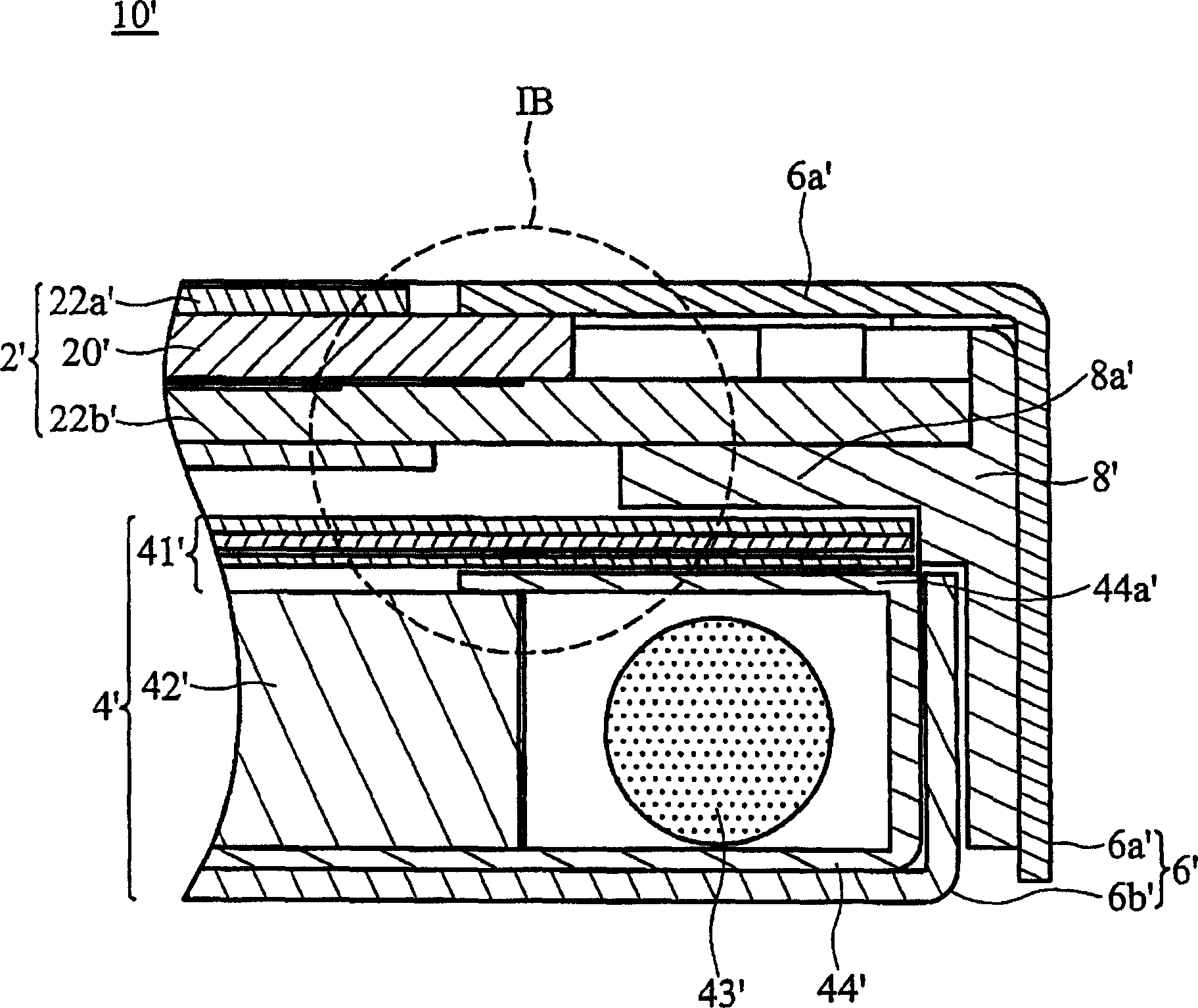
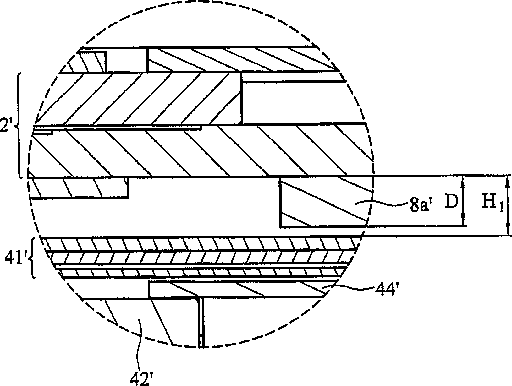
technical field [0001] The invention relates to a flat display, in particular to a flat display with a thinner backlight module. Background technique [0002] Flat panel displays, such as liquid crystal displays (TFT-LCDs), are widely used in various electronic products, such as notebook computers, desktop computers, televisions, car navigation systems, and mobile phones. In addition to the requirements of image quality and brightness, flat panel displays are increasingly focused on light and thin designs, but various components in the flat panel display play a certain role. [0003] FIG. 1 shows a schematic diagram of a conventional flat panel display. The liquid crystal display 10' includes a liquid crystal panel 2', a backlight module 4', a casing 6' and a plastic frame 8'. [0004] The liquid crystal panel 2' is mainly composed of a pair of transparent substrates 22a', 22b', and the liquid crystal 20' is placed between the transparent substrates 22a', 22b'. [0005] T...

Claims


Application Information

Patent Timeline
Patent Type & Authority Applications(China)
IPC IPC(8): G02F1/133G02F1/1333G02F1/1335
CPCG02B6/0088G02F1/133605G02B6/0055G02F1/133606G02F1/133615
Inventor 郭汉斌庄信源
Owner AU OPTRONICS CORP
Learn More