Spindle central oil feeding burner

A burner and shaft technology, which is applied to the oil burner and gas at the center of the shaft. It can solve the problems that affect the rotation of the fan blades, affect the uniformity of oil vaporization, and affect the rotational speed of the rotating shaft, and achieve the effects of uniform rotating speed of the rotating shaft, high oil vaporization rate and uniformity, and high combustion efficiency.

Inactive Publication Date: 2005-01-12
王战勇
View PDF1 Cites 4 Cited by
  • Summary
  • Abstract
  • Description
  • Claims
  • Application Information

AI Technical Summary

Problems solved by technology

But this burner has the following deficiencies: one is that the bearing part at the lower end of the rotating shaft (i.e. the oil pipe) adopts a dynamic seal structure, which will affect the rotating speed of the rotating shaft; The position affects the uniformity of oil vaporization; the third is that when the pressure of the air chamber increases, it will affect the rotation of the fan blades

Method used


Image

  • Spindle central oil feeding burner
  • Spindle central oil feeding burner
  • Spindle central oil feeding burner

Examples


Embodiment 1

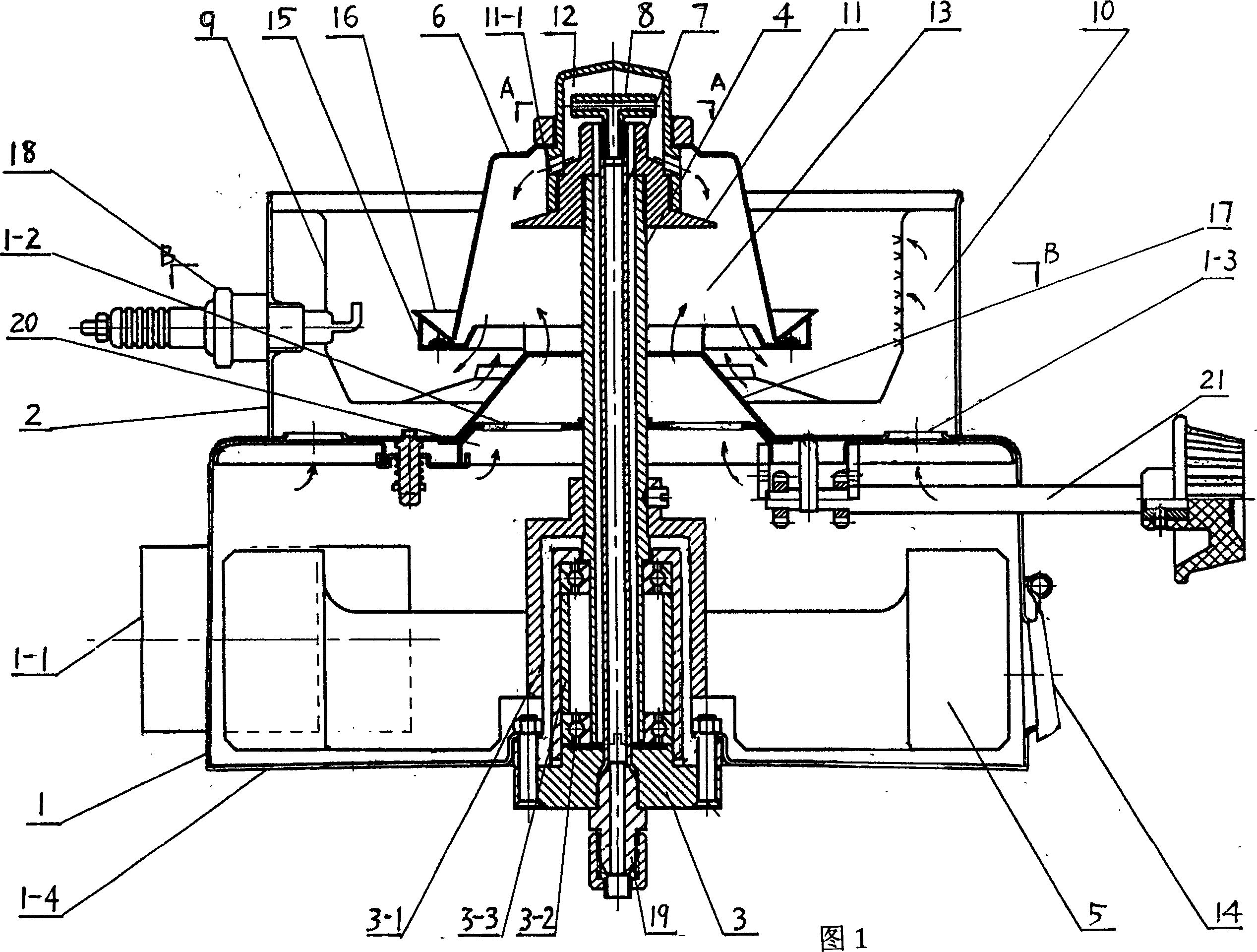
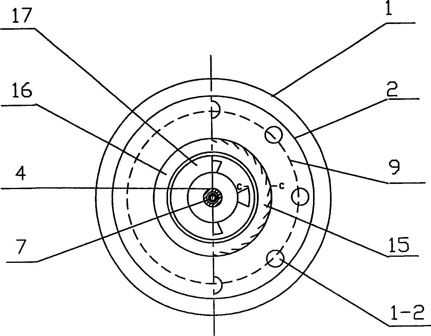
[0017] Example 1. See Figure 1. The central oil supply burner of the rotating shaft of this example includes two major parts: the air chamber shell 1 and the combustion chamber shell 2 on it; the combustion chamber 2 has a meshed combustion bowl 9 and an annular air chamber is formed between them. 10. Between the two shells, there are 8 tuyere 1-2, 1-3 arranged in an inner and outer ring shape each to form a gas channel (see image 3 ), the inner ring tuyere 1-2 is provided with a wind collecting hood 17 opposite to the vaporization rotating cap 6, the outer ring tuyere 1-3 is opposite to the annular air chamber; there can be an air volume adjustment plate 20 and a gear adjustment mechanism 21 under the inner and outer ring tuyere . The air chamber 1 is sealed with a base 1-4, and is provided with a tangential air inlet 1-1 and a pressure relief structure 14. The pressure relief structure is a gradually thicker gravity door cover; the bearing part 3 at the bottom supports a rotati...


PUM


Abstract

The rotation shaft oil/gas supplying burner consist sof air chamber caisng and combustor on the casing, which are communicated via gas channel. One rotating shaft supported with the bearing part in the bottom of the air chamber stretches through the channel to the combustor and has vaporizing rotary cap connected to its upper part and oil pipe and oil nozzle onside it. The combustor has burning bowl with small holes or meshes and circular air chamber formed into between. The present invention features that the oil pipe inside the rotation shaft is fixed and the evaporizing top cap with side hole in the top of the rotation shaft separates the rotary cap space into vaporizing chamber and mixing chamber. The present invention has the advantages of homogeneous rotation speed, high oil vaporizing rate and high homogeneity.

Description

Technical field [0001] The invention relates to an improvement of a burner for oil and gas, in particular to a burner with a central oil supply on a rotating shaft, which can also use gas. Background technique [0002] Chinese patent CN2586908Y discloses a "rotary shaft oil supply burner", which has a wind chamber shell with an air inlet and a combustion chamber shell on it. There is a gas channel between the two, and the bearing part at the bottom of the wind chamber supports A rotating shaft passes through the channel to the combustion chamber. The lower part of the rotating shaft is connected with a pneumatic impeller. The upper part of the rotating shaft is connected with a vaporization rotating cap. There is an oil pipe in the middle of the rotating shaft and the rotating shaft rotates at the same time. . However, the burner has the following shortcomings: First, the bearing part at the lower end of the shaft (ie, the oil pipe) adopts a dynamic seal structure, which will aff...

Claims


Application Information

Patent Timeline
Patent Type & Authority Applications(China)
IPC IPC(8): F23D11/10F23D11/38F23D11/40F23D11/44
Inventor 王战勇
Owner 王战勇
Why Eureka
Try Eureka