
Method of secondary side connecting reactive power generator of smelting transformer

A technology for power generators and transformers, applied in the direction of reactive power adjustment/elimination/compensation, reactive power compensation, etc., can solve the problem of reducing reactive power and harmonic current, cannot achieve dynamic real-time compensation and local compensation, limited and other problems to achieve the effect of eliminating harmonic current and realizing asymmetric control

Inactive Publication Date: 2005-01-12
西安汇丰电力设备有限公司
View PDF0 Cites 1 Cited by
  • Summary
  • Abstract
  • Description
  • Claims
  • Application Information

AI Technical Summary

Problems solved by technology

[0002] In order to ensure the power quality of power supply and consumption, and reduce the reactive power and harmonic current transmitted through the power grid, the power system generally installs reactive power compensation and harmonic elimination on the primary side of the smelting transformer, that is, the transmission system. This technology is currently relatively Mature technology and commonly used technology, but the use of primary side devices for compensation does not allow reactive power and harmonic current to flow on the shortest path, the purpose of on-site compensation cannot be achieved, and the effect of increasing production and reducing energy consumption is very limited
Since the secondary side of the smelting transformer and the lines on the secondary side are the source of reactive power and harmonics, the reactive power and harmonics must pass through the secondary side of the transformer and the lines on the secondary side and the reactive power compensation installed on the primary side. The device undergoes energy exchange, and there is a long exchange path, which cannot achieve dynamic real-time compensation and in-situ compensation.

Method used


Image

  • Method of secondary side connecting reactive power generator of smelting transformer
  • Method of secondary side connecting reactive power generator of smelting transformer
  • Method of secondary side connecting reactive power generator of smelting transformer

Examples


Embodiment 1

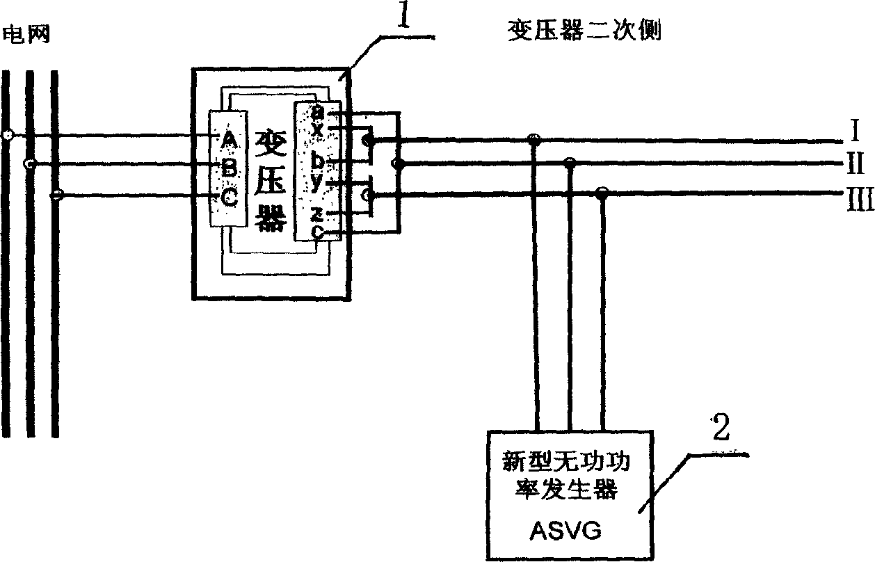
[0042] refer to figure 1 As shown, the smelting transformer 1 and the new reactive power generator 2 are included, and the new reactive power generator 2 is connected in parallel on the secondary side main circuit of the smelting transformer 1 .

[0043] The first end of the main circuit a-phase and c-phase winding of the secondary side of the smelting transformer is connected to phase II of the reactive power generator in parallel, and the first end of the main circuit b-phase winding is connected to the new type Phase I of the reactive power generator, three-phase secondary winding terminals y and z are connected in parallel to phase III of the new reactive power generator.

Embodiment 2

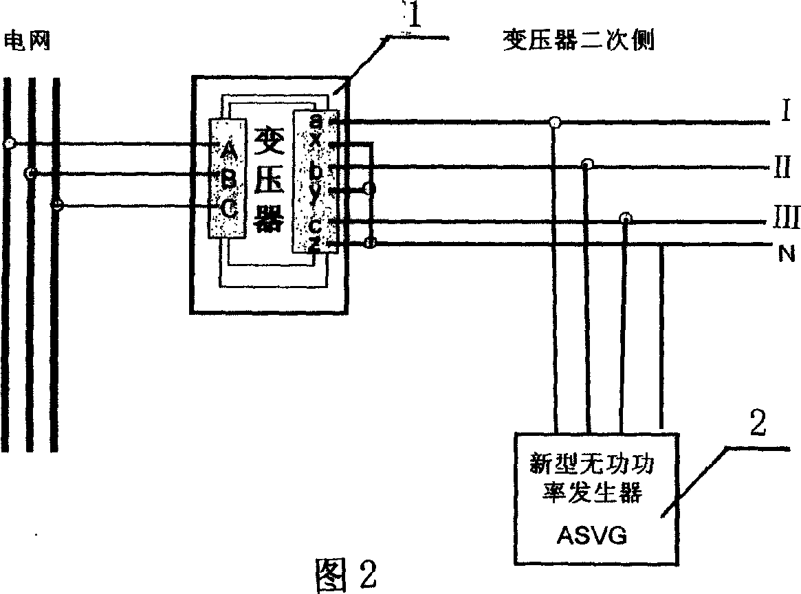
[0045] As shown in Fig. 2, including the smelting transformer 1 and the new reactive power generator 2, the three-phase four-wire circuit formed by the phase modulation of the first and the end of the three-phase main circuit winding on the secondary side of the smelting transformer 1 is connected in parallel with the new reactive power generator. Reactive Power Generator 2.

[0046] Phases a, b, and c of the main circuit are respectively connected to phases I, II, and III of the new reactive power generator in turn, and the terminals x, y, and z of the secondary winding of the three-phase four-wire system are connected in parallel to the new reactive power generator on the zero line N of device 2.

Embodiment 3

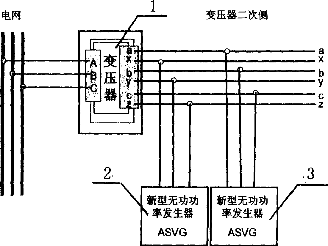
[0048] image 3 As shown, including the smelting transformer 1 and the new reactive power generator 2, the main circuit a, b, c phases and x, y, z are respectively connected in parallel with two sets of new reactive power generators 2; or the main circuits a-x, b-y, c-z formed by the non-phase adjustment of the first end and the end of the three-phase main circuit winding on the secondary side of the smelting transformer 1 are respectively on the single-phase A single-phase novel reactive power generator 2 is connected in parallel.

[0049]Including the AC smelting transformer 1 and the new reactive power generator 2, on the secondary side of the smelting transformer 1, the three-phase main circuit a, b, c three-phase secondary winding head end and the three-phase secondary winding end x, y Two new reactive power generators 2 and 3 of the same model are respectively connected in parallel on z and z respectively.

[0050] Or the first end of the three-phase main circuit a, b,...


PUM


Abstract

The method includes following approaches: (1) a new type reactive power generator is connected in parallel to three phases of major loop at secondary side in three phase three wire system or three phase four wire system; (2) or a new type reactive power generator is connected in parallel to head part of secondary winding of three phases of major loop at secondary side in three phase three wire system as well as a new type reactive power generator is connected in parallel to tail part of secondary winding of three phases; (3) or in building block mode, multiple combined new type reactive power generators are connected in parallel. Disclosed generator takes in and sends out large reactive components, compensates current. Features are: quick response, accurate control of voltage.

Description

technical field [0001] The utility model relates to reactive power compensation and harmonic elimination of electric power grid, in particular to a method for connecting a novel reactive power generator on the secondary side of a smelting transformer. Background technique [0002] In order to ensure the power quality of power supply and consumption, and reduce the reactive power and harmonic current transmitted through the power grid, the power system generally installs reactive power compensation and harmonic elimination on the primary side of the smelting transformer, that is, the transmission system. This technology is currently relatively Mature technology and commonly used technology, but the use of primary side devices for compensation does not allow reactive power and harmonic current to flow on the shortest path, the purpose of on-site compensation cannot be achieved, and the effect of increasing production and reducing energy consumption is very limited . Since the...

Claims


Application Information

Patent Timeline
Patent Type & Authority Applications(China)
IPC IPC(8): H02J3/18
CPCY02E40/30
Inventor 白玉龙王昀睿
Owner 西安汇丰电力设备有限公司
Learn More