Slide core unit

A core mold and mold technology, which is applied in the field of sliding core mold devices, can solve the problems of increased maintenance cost of a forming metal mold 1, and achieve the effects of reduced maintenance cost and simplified structure.

Inactive Publication Date: 2005-01-12
竹元 通则 +1
View PDF0 Cites 13 Cited by
  • Summary
  • Abstract
  • Description
  • Claims
  • Application Information

AI Technical Summary

Problems solved by technology

[0010] However, when the spring 3e is provided on the sliding core 4, it is necessary to form a hole 4c for embedding the spring 3e in the sliding core 4, so there is a problem that the sliding core 4 is enlarged.
Moreover, since the groove-shaped rail portion 3b that slidably supports the sliding mandrel 4 is directly formed on the movable mold 3, when the rail portion 3b is worn due to the sliding, it is necessary to replace the entire movable mold 3, resulting in forming problems. The problem that the maintenance cost of metal mold 1 has increased significantly

Method used


Image

  • Slide core unit
  • Slide core unit
  • Slide core unit

Examples


no. 1 Embodiment approach

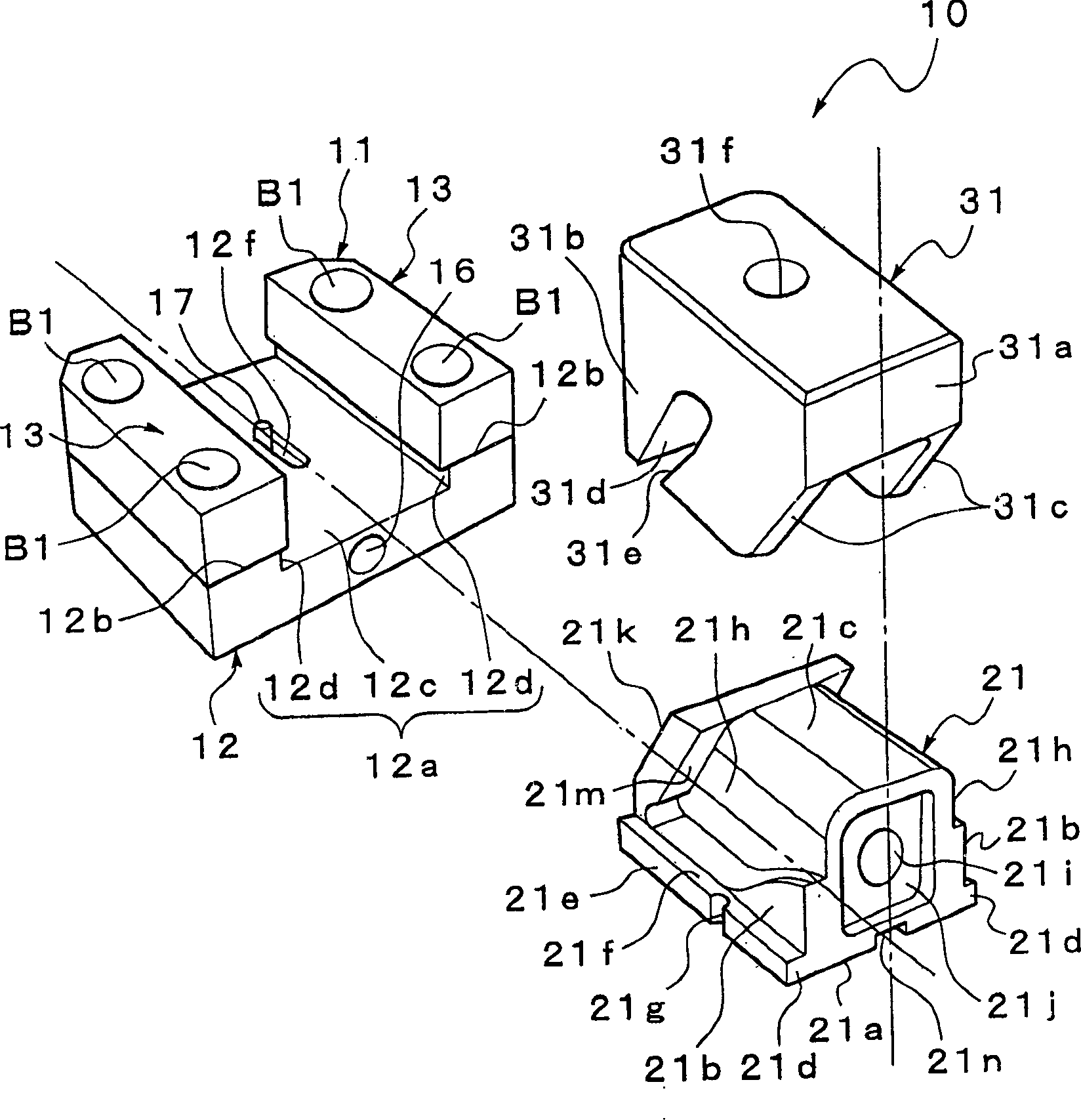
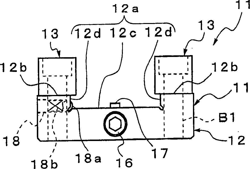
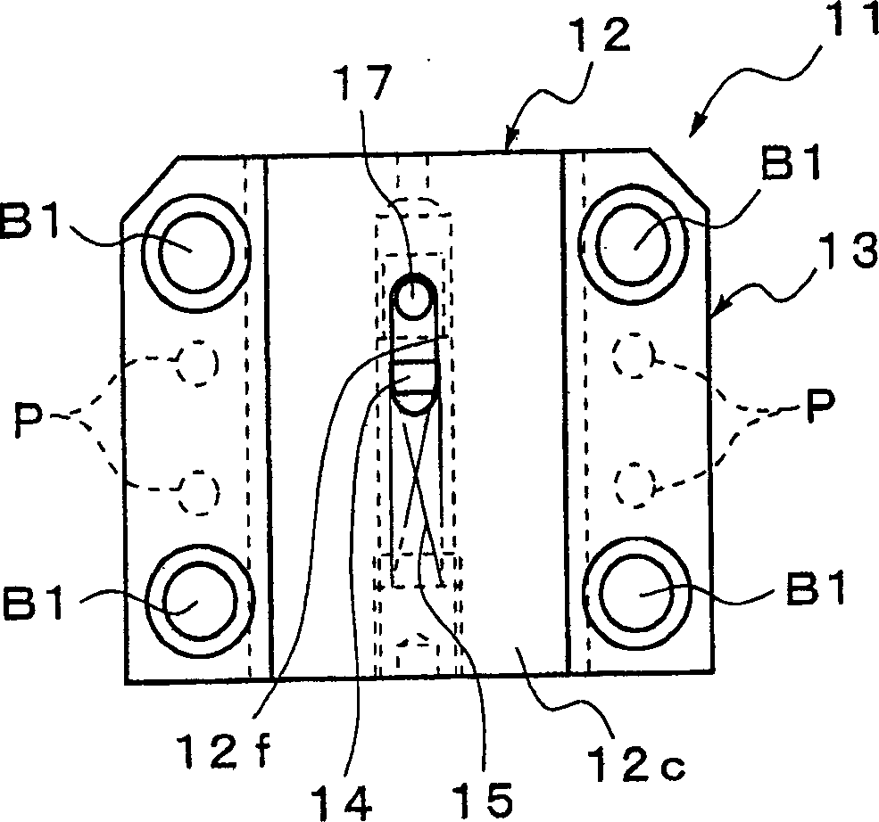
[0050] First, refer to Figure 1 to Figure 9 The first embodiment will be described. However, the same symbols are assigned to the same components as those in the prior art example, and the description thereof will be simplified.

[0051] Such as Figure 8 and Figure 9 As shown, the slide core mold device 10 shown in this embodiment is set in the forming metal mold 8 . The molding metal mold 8 has a pair of molds, that is, a fixed mold 6 and a movable mold 7 that are freely openable and closed, and these fixed molds 6 and movable molds 7 are respectively fixed to fixed plates of an injection molding machine (not shown). and movable disk. The injection molding machine drives the movable mold 7 in the opening and closing direction by moving the movable platen in the forward and backward direction relative to the fixed platen.

[0052] In addition, if Figure 8 As shown, when the molding metal mold 8 is in the mold-closed state, the mating surfaces 6a, 7a of the fixed mold...

no. 2 Embodiment approach

[0085] Next, refer to Figure 12 ~ Figure 1 6b to describe the second embodiment of the present invention. However, the same reference numerals are given to the same components as those of the first embodiment, and the description thereof will be simplified.

[0086] The sliding core device 10A shown in this embodiment has a configuration in which a sliding core 21A is provided with an urging mechanism that acts on the sliding core 21A in a direction retreating from the chamber 8a with respect to the guide member 11A. Apply force.

[0087] Such as Figure 12 , Figure 13a and Figure 13b As shown, the guide member 11A is formed in the shape of a square rod, and a groove-shaped rail portion 11 b linearly extending in the axial direction is formed on an upper surface 11 a of one side thereof. The rail portion 11b has inner surfaces 11d vertically standing up from both ends in the width direction of the planar bottom surface 11c, and sections protruding inward from each othe...


PUM


Abstract

The configuration is such that there are provided a slide core 21 (21A) disposed to be movable toward and away from a cavity (molding space) 8a and driven at least in the direction toward the cavity 8a according to the closing action of a mold 8, and a guiding member (guiding means) 11 (11A) disposed at least on one mold member 7 of the mold and having a groove-shaped rail part 12a for supporting the slide core 21 in the directions toward and away from the cavity 8a, wherein one member out of the slide core 21 and guiding means 11 is provided with urging means for urging the slide core relative to the guiding member 11 in the direction away from the cavity 8a. This configuration makes it possible to reduce the size and the maintenance cost of the slide core.

Description

technical field [0001] The present invention relates to a sliding mandrel assembly arranged in a forming metal mold. Background technique [0002] For example, as a forming metal mold used in an injection molding machine, such as Figure 19a and Figure 19b The metal mold shown is known. In this figure, 1 is a forming die, and the forming die 1 is composed of a pair of dies including a fixed die 2 and a movable die 3 . The fixed mold 2 and the movable mold 3 are respectively fixed to, for example, a fixed platen and a movable platen of an injection molding machine (not shown). By moving the movable plate to the fixed plate, the movable mold 3 and the fixed mold 2 become closed, and in addition, by moving the movable plate in a direction away from the fixed plate, the movable mold 3 moves away from the fixed mold 2. Leave the open state. [0003] In addition, in the closed state of the molding die 1, the mating surfaces 2a, 3a of the fixed die 2 and the movable die 3 are ...

Claims


Application Information

Patent Timeline
Patent Type & Authority Applications(China)
IPC IPC(8): B29C33/44B29C45/33B29C45/44
CPCB29C33/44Y10S425/058B29C45/332B29C45/44B29C45/33
Inventor 竹元通则市川泉
Owner 竹元 通则
Why Eureka
Try Eureka