
Infinitely variable adjustable gearbox

A technology of transmission and differential transmission, which is applied in the direction of differential transmission, transmission, transmission control, etc., can solve problems such as unfavorable transmission, and achieve the effect of torque transmission expansion

Inactive Publication Date: 2005-01-19
乌尔里克·罗斯
View PDF2 Cites 12 Cited by
  • Summary
  • Abstract
  • Description
  • Claims
  • Application Information

AI Technical Summary

Problems solved by technology

On the other hand, such a transmission is disadvantageous especially in certain driving situations

Method used


Image

  • Infinitely variable adjustable gearbox
  • Infinitely variable adjustable gearbox
  • Infinitely variable adjustable gearbox

Examples


Embodiment Construction

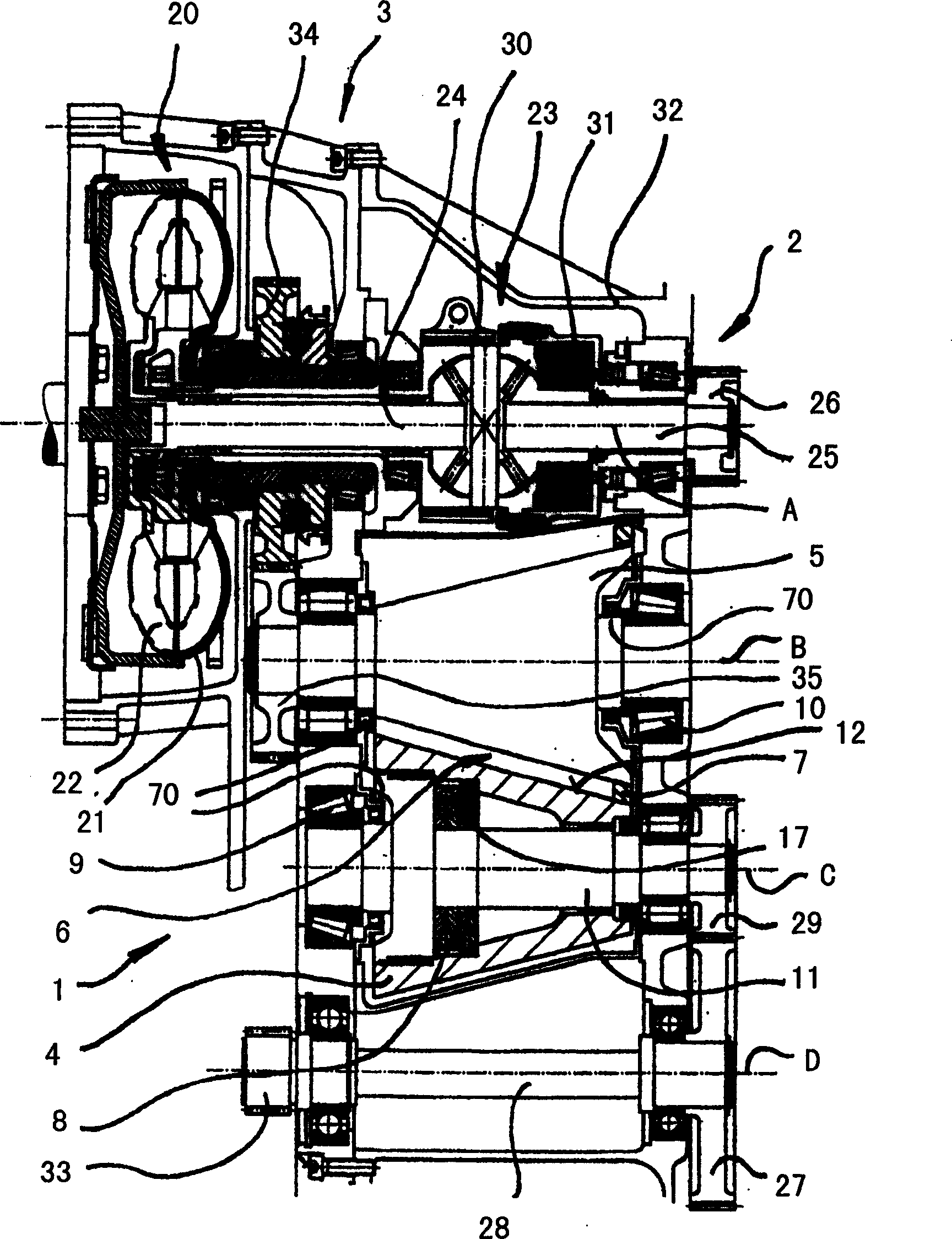
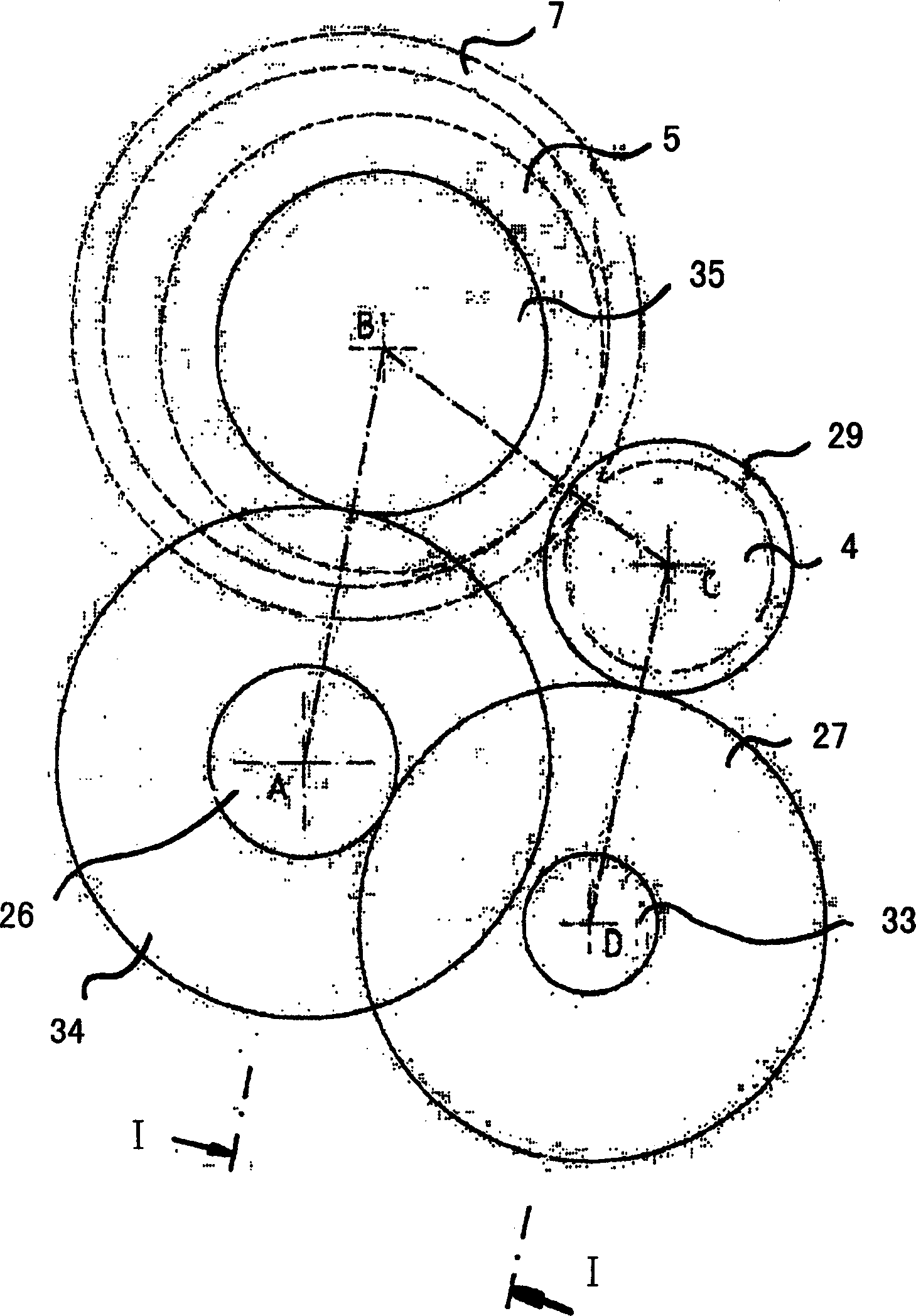
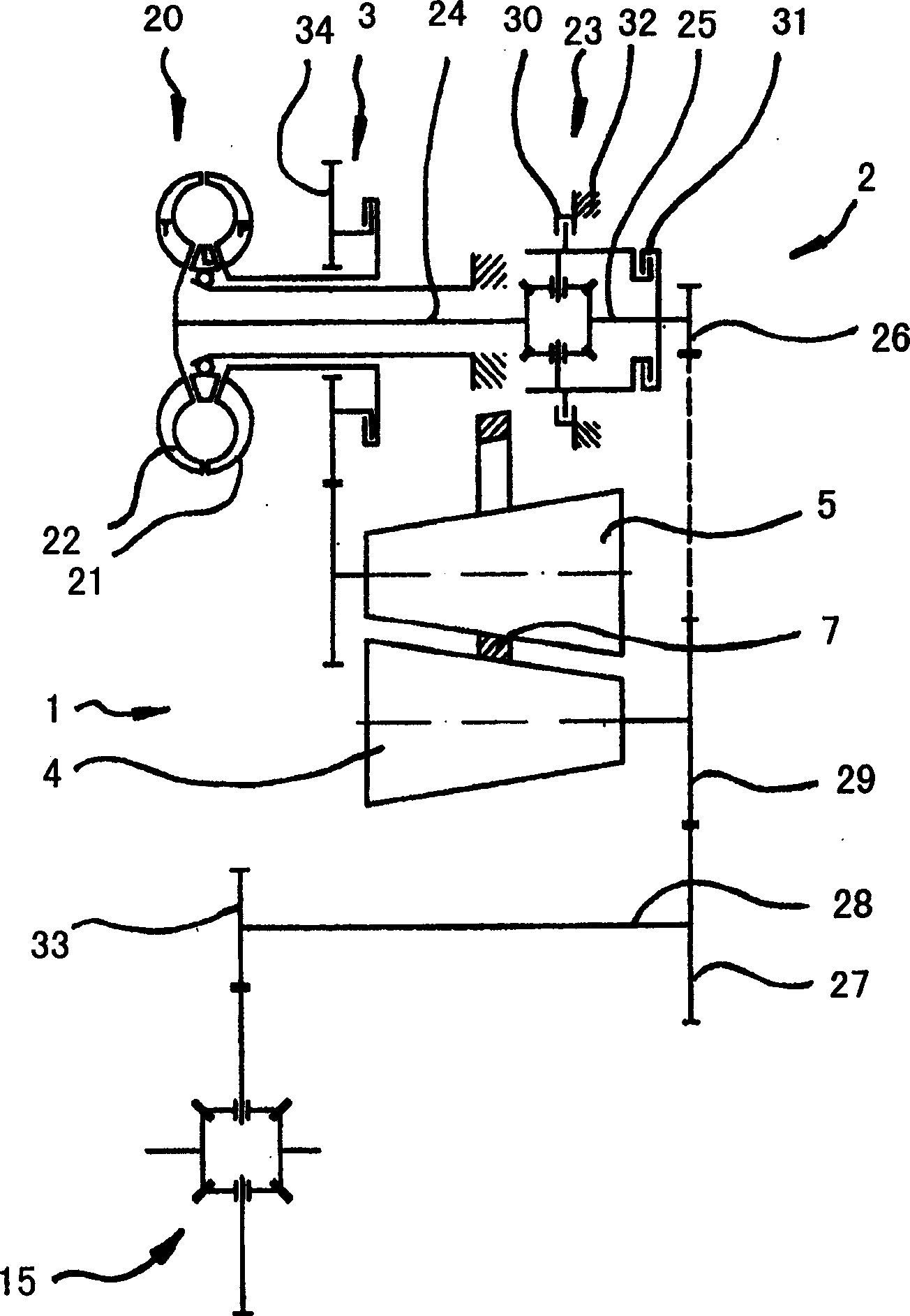
[0068] Figure 1-3 The transmission shown essentially comprises two transmission paths 1 , 2 which can be selectively connected into one transmission path via a synchronous transmission 3 .

[0069] Here, the first drive path 1 has a conical friction ring drive with two opposing cones 4 , 5 arranged in such a way that a gap remains between the cones 4 , 5 . A gap 6 in which a friction ring 7 moves around the cone 5 . In order for the conical friction ring transmission to be able to transmit torque, the cone 4 includes a hold-down device 8, which tensions the two cones 4 between the clamping bearings 9, 10 with a variable pressing force , 5.

[0070] The cone 4 has a running surface 12 on the one hand and a clamping part 11 on the other hand, between which a pressing device 8 acts, wherein the pressing device 8 can hold the clamping part 11 against the running surface 12 As a result, the clamping part 11 bears on the fastening bearing 9 on the one hand and presses the runnin...


PUM


Abstract

A transmission device with a steplessly adjustable branch transmission mechanism has two parallel transmission paths, wherein the steplessly adjustable branch transmission mechanism is arranged in the first transmission path of the two transmission paths .

Description

technical field [0001] The invention relates to a transmission device with a steplessly adjustable branch transmission mechanism. Such transmissions are known per se, for example from EP0878641A1 and EP0980993A2. Although only conical friction ring transmissions are described in these documents, the invention can also be used in conjunction with other continuously variable transmissions (CVT). Background technique [0002] Such a continuously variable transmission is advantageous in many driving situations, in particular with regard to driving comfort or the utilization of the torque provided by the drive. On the other hand, such a transmission is disadvantageous especially in certain driving situations. The latter can be, for example, when driving slowly, reversing or under constant load. Contents of the invention [0003] The object of the present invention is to provide a transmission with an infinitely adjustable branch transmission in which problems in special driv...

Claims


Application Information

Patent Timeline
IPC IPC(8): F16D3/06F16H15/00F16H15/38F16H15/42F16H37/02F16H61/00F16H61/12
CPCF16H37/0853F16H37/021F16H15/42Y10T74/19344Y10T477/69363F16H61/66272F16H37/022F16H48/08
Inventor 乌尔里克·罗斯W·布兰维特C·德雷格尔
Owner 乌尔里克·罗斯
Learn More