

Needle valve pair with forced lubrication and cooling
A forced lubrication, needle valve technology, applied in engine components, machines/engines, charging systems, etc., can solve problems such as poor atomization, energy waste, environmental pollution, etc., and achieve the effect of novel structure and significant social benefits
Inactive Publication Date: 2005-01-26
李明海
View PDF0 Cites 5 Cited by
- Summary
- Abstract
- Description
- Claims
- Application Information
AI Technical Summary
Problems solved by technology
Therefore, it is very easy to cause the needle valve to be strained or stuck. In the slightest, it will cause oil dripping and poor atomization of the nozzle, so that the fuel cannot be fully burned, and the diesel engine emits black smoke, resulting in energy waste and environmental pollution. In severe cases, the diesel engine cannot work normally. Work
Method used
View moreImage
Smart ImageViewing Examples

Examples
Embodiment Construction
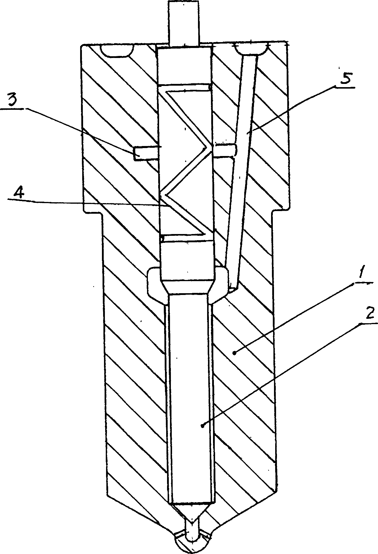
[0009] exist figure 1 In the specific embodiment shown, the valve body 1 processed with the oil inlet passage 5 is loaded into the valve core 2, and a spiral oil groove 4 is processed on the circumferential surface guided by the valve core 2, corresponding to the spiral oil groove 4. A pressure equalizing groove 3 communicating with the spiral oil groove 4 is opened at the center of the valve body 1 so that the pressure equalizing groove 3 communicates with the oil inlet passage 5 .
Login to View More PUM
 Abstract
This invention involves one kind to have the forced lubrication and the cooling pin valve partner, this invention is in the original pin valve partner, has the helix fuel tank on the valve core, corresponds with the helix fuel tank on the valve body opens has presses the trough, presses the trough and the helix fuel tank, enters oil lead connects, the fuel oil from enters oil lead enters, first enters presses the trough, the helix fuel tank, then seeps along the helix fuel tank covers in the friction contact face between Yu Faxin yu Fati, thus carries on the high pressure forced lubrication and cooling. This invention greatly reduced and avoids the pin valve partner's deactivation, pulls the wound, the movement is not nimble and so on the phenomenon, thus has guaranteed diesel engine instruction and so on work efficiency and reliability. This invention has the structure novel, the science reasonable, simple is practical, the energy conservation, does not have characteristic and so on pollution.
Description
technical field [0001] The invention relates to a needle valve coupler for diesel engine fuel atomization, especially a needle valve coupler capable of forced lubrication and cooling. Background technique [0002] At present, the needle valve couple used by domestic and foreign diesel engines to atomize fuel oil is composed of a valve body and a valve core. , the oil inlet channel connected with the oil supply ring, after the fuel enters the oil supply ring from the oil inlet channel, the high-speed reciprocating movement of the valve core in the valve body makes the fuel drip and spray out from the nozzle at the lower part of the valve body fully combustion. According to the requirements, the assembly gap between the head of the valve core and the valve body is quite small, 0.002-0.004mm, and the friction surface between the valve core and the valve body is lubricated only by the fuel that naturally penetrates upward in the oil supply ring. lubricating. Under such a smal...
Claims
Login to View More Application Information
Patent Timeline
 IPC IPC(8): F02M61/06
Inventor李明海
Owner李明海