Binding clamps and folders

A technology for binding clips and file folders, applied in file folders, printing, etc., can solve problems such as the inability to maintain the state of binding, and achieve the effect of simple structure

Inactive Publication Date: 2005-02-02
KOKUYO CO LTD
View PDF0 Cites 4 Cited by
  • Summary
  • Abstract
  • Description
  • Claims
  • Application Information

AI Technical Summary

Problems solved by technology

[0003] However, in the binding folder of such bead folders, the sliding body becomes an essential component, and the sliding body must be moved to a predetermined position, otherwise the bound state cannot be maintained.
Furthermore, the base plate must be provided with guide rails for moving the slider, and it must be formed in a structure that cannot fall off, so there is still the inconvenience that the binding plate member cannot be obtained as an integrally molded product.

Method used


Image

  • Binding clamps and folders
  • Binding clamps and folders
  • Binding clamps and folders

Examples


no. 1 approach

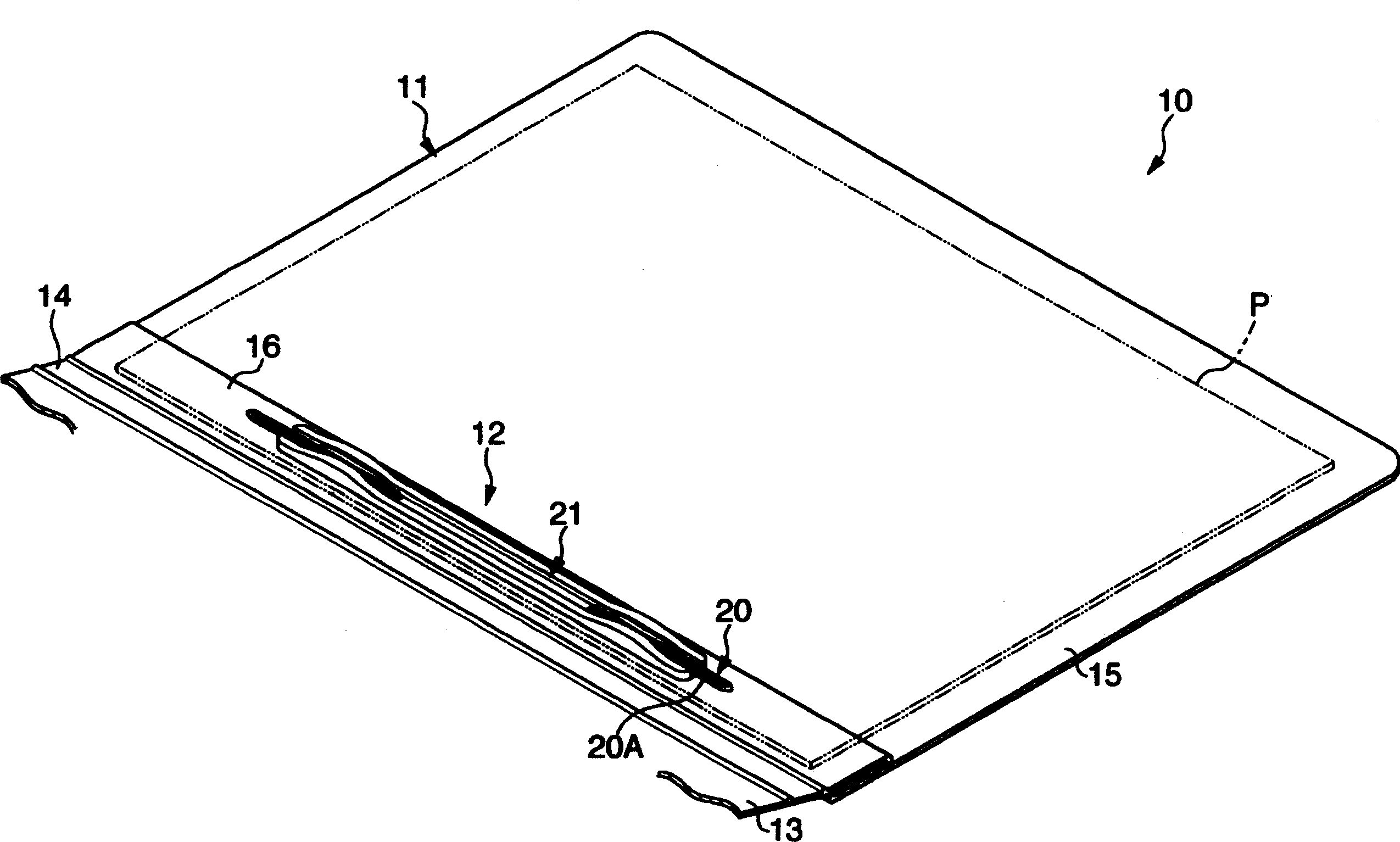
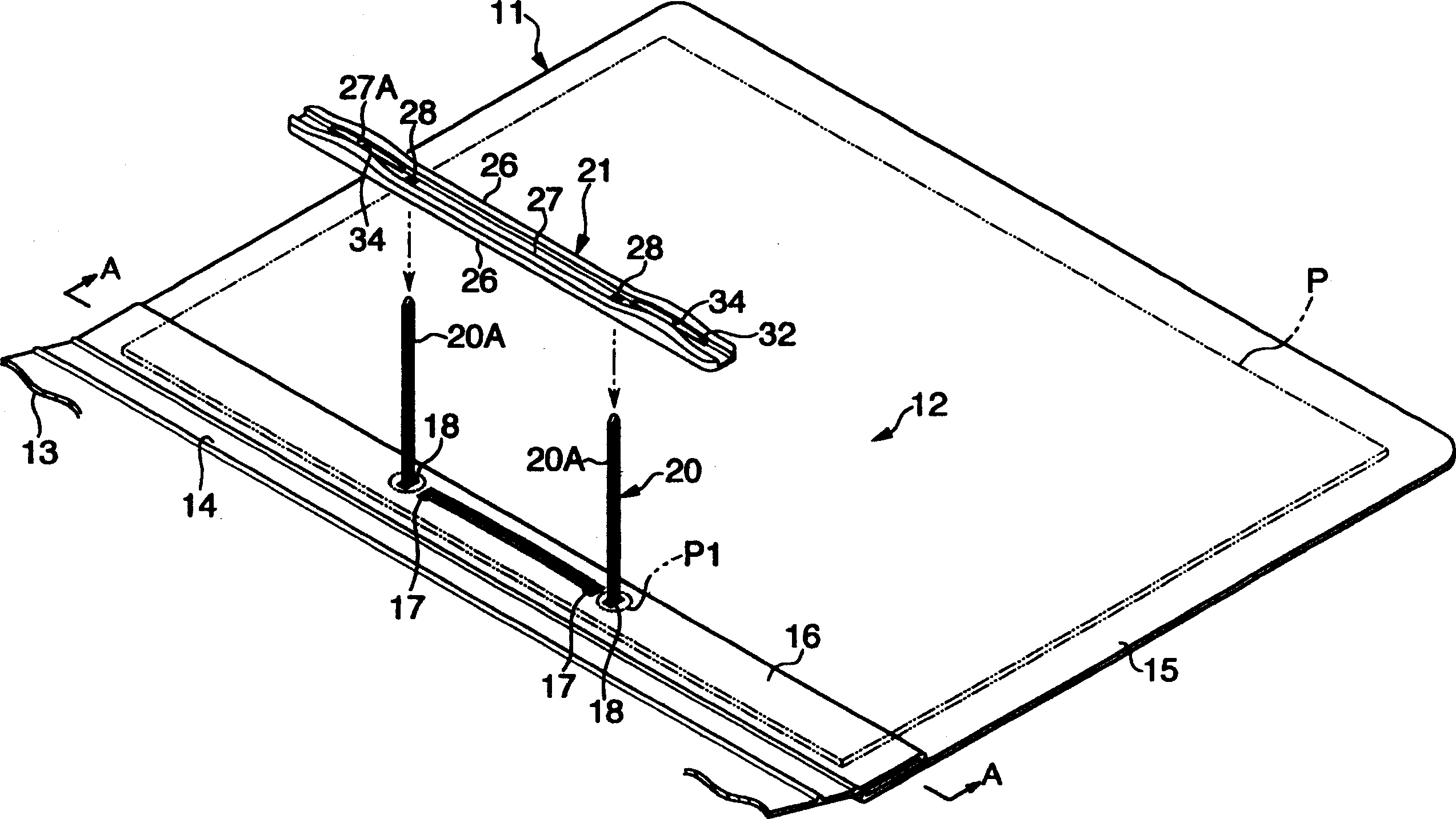
[0060] figure 1 A schematic perspective view showing the opened state of the folder of the first embodiment, figure 2 A schematic perspective view showing the state where the binding plate part is removed from the binding tape. In these figures, the file folder 10 is composed of a leather body 11 and a binder 12 attached to the leather body 11 . The clip leather body 11 consists of a clip surface 13, a clip bottom 15 connected to the clip surface 13 via the clip back 14, and from the inner side of the clip back 14, that is, the junction of the clip back 14 and the clip bottom 15, to the inside. It consists of a sheet-shaped mounting part 16 folded in a double-layered state. like figure 2 As shown, on the two regions of the up and down direction of the mounting part 16, a pair of inner holes 17, 17 and a pair of outer holes 18, 18 are formed. Using these inner holes 17 and outer holes 18, the binding clip 12 It can be freely disassembled relative to the skin body 11 .

...

no. 2 approach

[0072] Second, refer to Figure 8 to Figure 10 A second embodiment of the present invention will be described. In addition, in the following description, the same code|symbol is used for the part which is substantially the same as that of 1st Embodiment, and the description is abbreviate|omitted.

[0073] This second embodiment is characterized in that it is provided with a handle portion 40 for easier pinching when the above-mentioned binding plate member 21 is removed. More specifically, in the base plate 25, a pair of side walls 2626, that is, the side walls 26, 26 located in the central region between the insertion paths 28, 28, are formed on the inside of the base plate 25 in the width direction. Positionally, thus, a structure is formed in which the handle portion 40 is formed on the upper part of the side walls 26 , 26 . In addition, on the lower surface side of the substrate 25, on the inner side immediately adjacent to the insertion paths 28, 28, spacers 42, 42 faci...


PUM


Abstract

The file 10 is composed by installing the binding tool 12 to an inner surface side of a cover body 11. The binding tool 12 comprises the binding cord 20 supported by the cover body 11 and a binding board member 21 capable of being assembled by inserting a tip side of the binding cord 20 and equipped with a receptive groove 27A of binding cord 20. The binding cord 20 has an almost strip shape formed by connecting paper strings or twisted paper strings 20A almost parallelly with each other, and can be inserted into and removed from the receptive groove 27A by flexible deformation of the binding cord 20.

Description

technical field [0001] The present invention relates to a binder clip and a folder, and more specifically relates to a reduction in the number of parts and ease of operation when adding, deleting, and arranging files, and at the same time reducing the time required for resource regeneration or disposal. Limitations of binders and folders. Background technique [0002] A well-known folder called a batten file is composed of a cover body and a binder provided on the back side of the cover body. The binder clip is mounted on a sheet-shaped mounting portion that is folded into the back side of the clip body and is provided along the vertical direction of the clip body. On the mounting part, two holes are respectively formed in two regions along the longitudinal direction (up-and-down direction of the file folder), and the two holes are used to support a pair of belt-shaped sheets made of plastic. Constitute the structure of the base region of the binder. In addition, the bind...

Claims


Application Information

Patent Timeline
Patent Type & Authority Applications(China)
IPC IPC(8): B42F13/06
Inventor 小池诚一辻野伸明
Owner KOKUYO CO LTD
Why Eureka
Try Eureka