Spinning machine with compressing apparatus

A compression device and spinning machine technology, applied in spinning machines, textiles, papermaking, drafting equipment, etc., can solve the problem that the fiber structure is not fully guided

Inactive Publication Date: 2005-02-02
MASCHINENFABRIK RIETER AG
View PDF4 Cites 4 Cited by
  • Summary
  • Abstract
  • Description
  • Claims
  • Application Information

AI Technical Summary

Problems solved by technology

[0004] The problem with processing certain materials with conveyor elements with smooth surfaces is that the fiber structure is not sufficiently guided, especially with wool and mixed fibers

Method used


Image

  • Spinning machine with compressing apparatus
  • Spinning machine with compressing apparatus
  • Spinning machine with compressing apparatus

Examples


Embodiment Construction

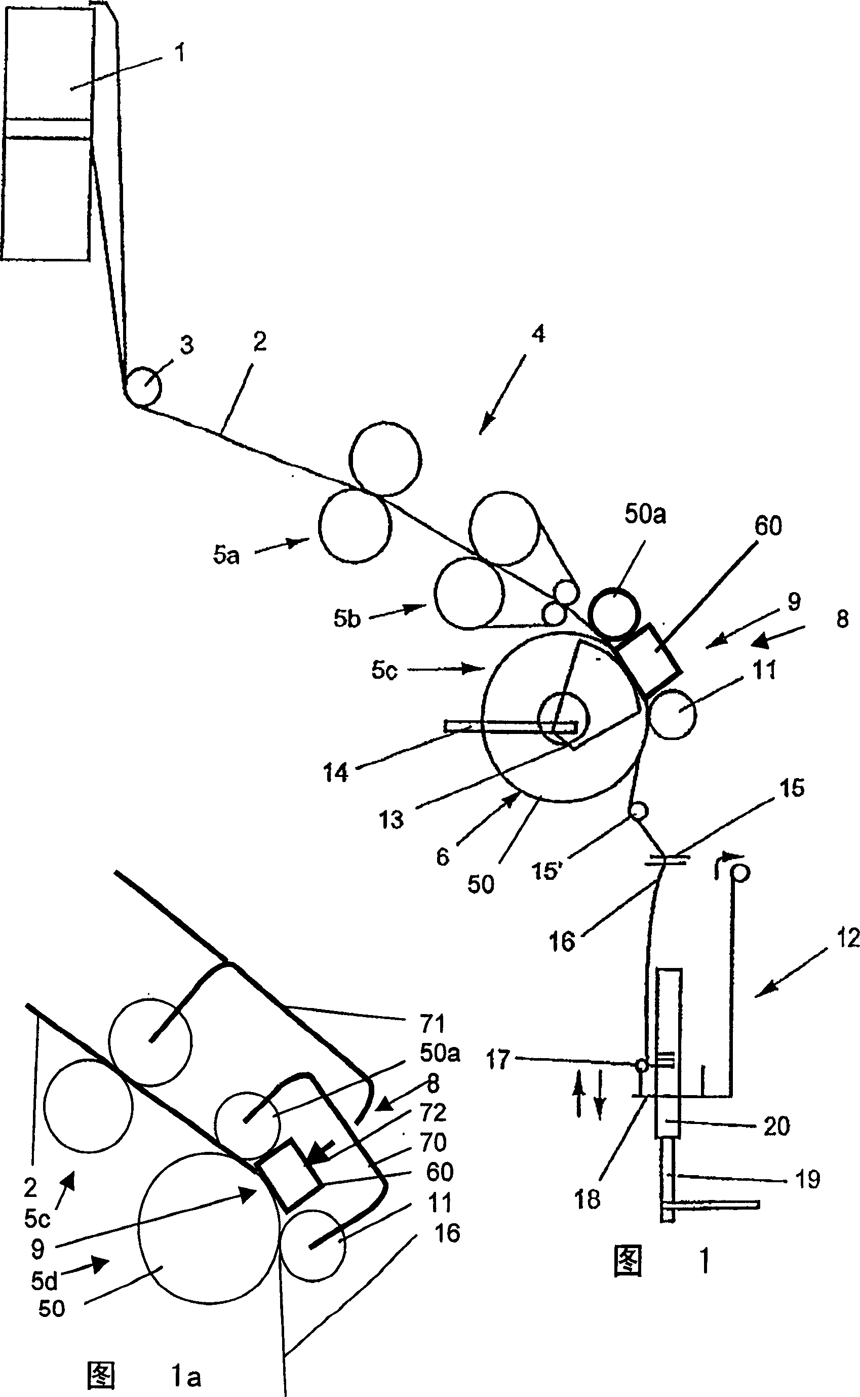
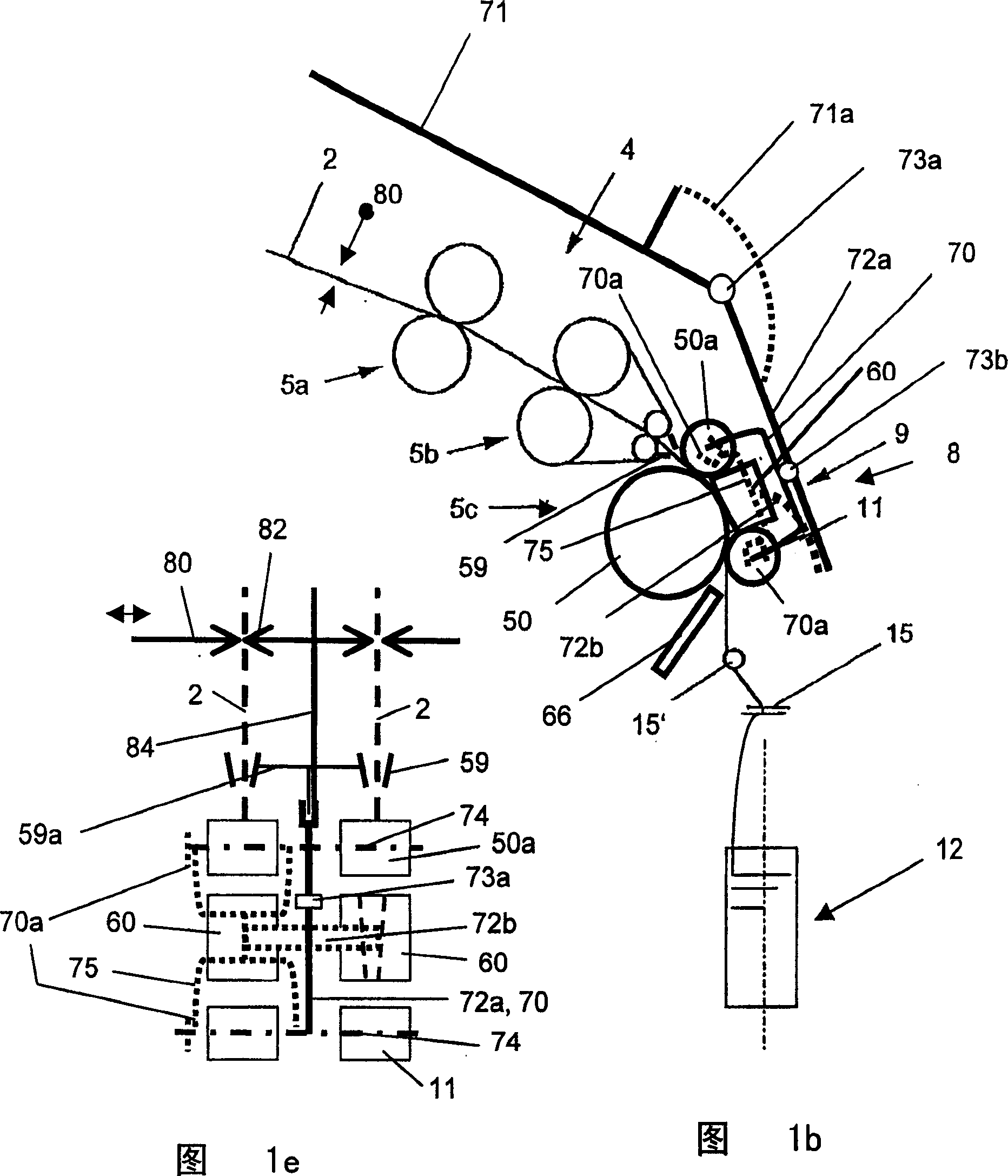
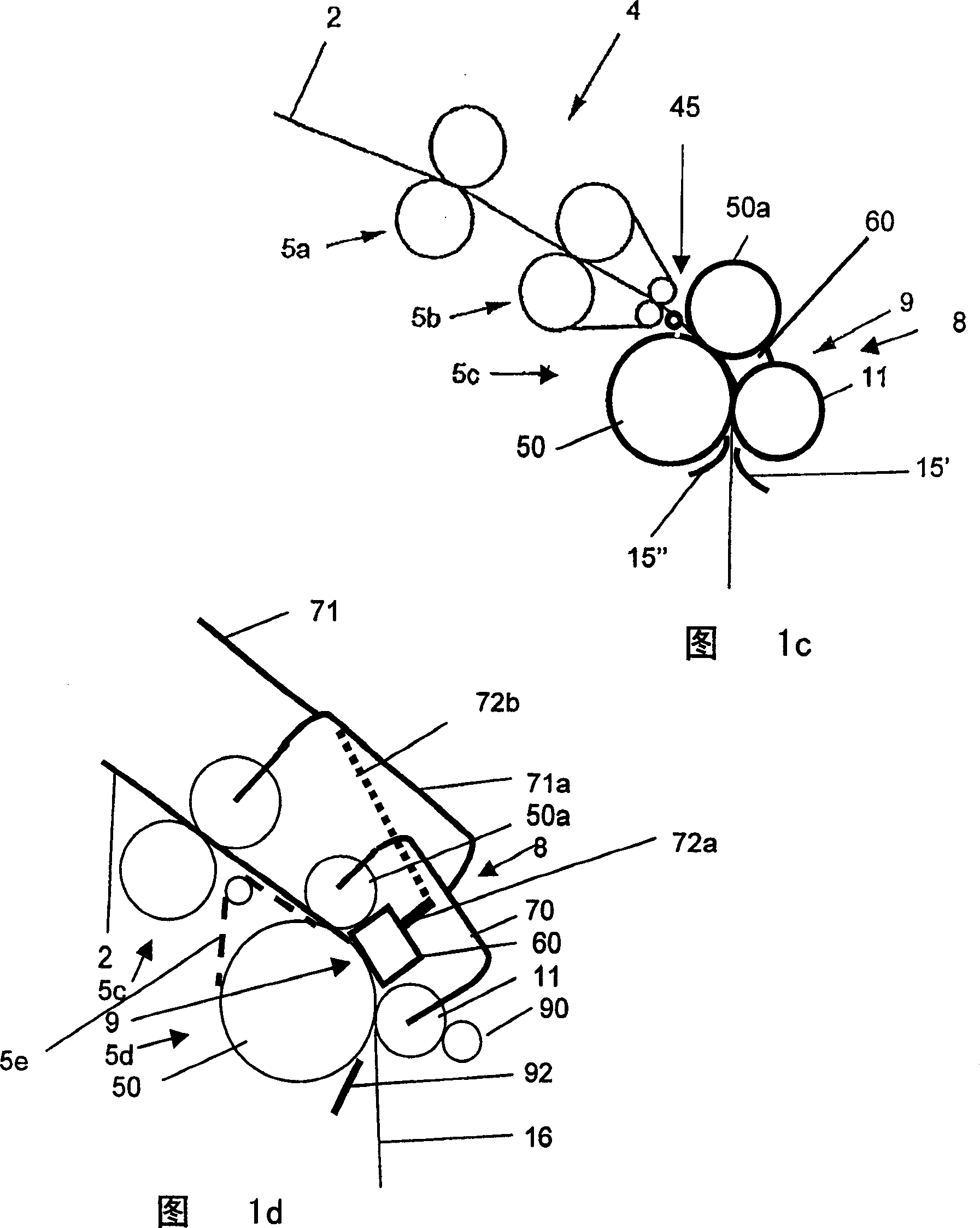
[0052] In a conventional spinning machine, the material supply 1 of FIG. 1 consists of cans or roving bobbins or rubbing bobbins. The fiber structure 2 is guided from the can to the drafting device. In the case of roving bobbins or rubbed bobbins, the roving is drawn from the circumference of the bobbins. The fiber structure, ie the roving yarn or fiber structure, enters the region of the drafting device 4 via a deflection device. The drafting unit consists of pairs of conveyor rollers, some of which are belted. The fibrous structure 2 is drafted only weakly between the first and second pair of delivery rollers 5a and 5b, and strongly between the second and subsequent pair of rollers 5c, so that a draft ratio of more than 100 can be achieved.

[0053] The drawn fiber structure is gripped between the gripping roller 50 a and the roller 6 and then compressed on the compression device 8 . The width of the fibrous structure leaving the drafting device 1 gradually decreases duri...


PUM


Abstract

The invention relates to a spinning machine with a drafting device (4) and a compression device (8); the compression device (8) is connected with the drafting device (4); the spinning machine comprises a conveying element (50) for conveying the drafted fibre texture (2) and a compression element (60) in the compression device (8), the compression element (60) extends along the surface of the conveying element (50). The invention is characterized in that, air is sucked into a guiding part (61), and the guiding part (61) is in the compression element (60) for compressing the fibre texture (2); at least one hole (62a, 63a) is communicated with the slots (61, 61a, 61b) for drawing in air.

Description

technical field [0001] The invention relates to a spinning machine with a compression device according to the preamble of claim 1 . Background technique [0002] A general device is known from US-A4488397, in which the fibrous structure is guided on a moving guide surface of a compression element, which exerts a traction force on the fibrous structure, flows laterally onto the fibrous structure and is drawn Air drawn into the interior of the guide surface deposits the outer fibers protruding from the fibrous structure onto the fibrous structure. Furthermore such a conveying element prevents the initiation of a rotational movement of the fiber structure or yarn downstream of the conveying element if a rotating application device is arranged downstream of the conveying element. On the spinning machine, such a compression device is preferably arranged between the drafting device and the ring spinning device, so that the conveying element can be a delivery roller of the draftin...

Claims


Application Information

Patent Timeline
Patent Type & Authority Applications(China)
IPC IPC(8): D01H5/26D01H5/72D01H5/74D01H13/04
CPCD01H5/72D01H5/74D01H13/04
Inventor D·迪特里希A·里什K·施内贝格尔C·格里斯哈默
Owner MASCHINENFABRIK RIETER AG
Why Eureka
Try Eureka