Rolling bearing for a wheel of vehicle and a semi-float type bearing apparatus having it

A rolling bearing and wheel technology, which is applied to devices using electric/magnetic methods, rolling contact bearings, roller bearings, etc., can solve the problems of slow perception of rotational speed, enlarged air gap, and inability to perceive rotational speed sensitively enough. Achieve the effect of increased strength and simplified assembly

Active Publication Date: 2005-02-02
NTN CORP
View PDF1 Cites 15 Cited by
  • Summary
  • Abstract
  • Description
  • Claims
  • Application Information

AI Technical Summary

Problems solved by technology

[0008] However, in such a conventional rolling bearing for a wheel, the pulsator ring 71 is arranged in the radial direction, and the rotation speed is detected from the outside in the axial direction by the detection sensor 75 through the cover member 72. Therefore, it is difficult to ensure sufficient space due to the restriction of the radial space of the bearing. The area of ​​the pulse generator ring 71 has the disadvantage that the perception of the rotational speed becomes dull
In addition, the shield member 72 can be used to prevent dust or sand particles from entering the encoder 71b from the outside of the bearing, but on the other hand, the air gap between the encoder 71b and the detection sensor 75 becomes large, and there is a problem that the rotational speed cannot be sensed sufficiently sensitively.

Method used


Image

  • Rolling bearing for a wheel of vehicle and a semi-float type bearing apparatus having it
  • Rolling bearing for a wheel of vehicle and a semi-float type bearing apparatus having it
  • Rolling bearing for a wheel of vehicle and a semi-float type bearing apparatus having it

Examples


Embodiment Construction

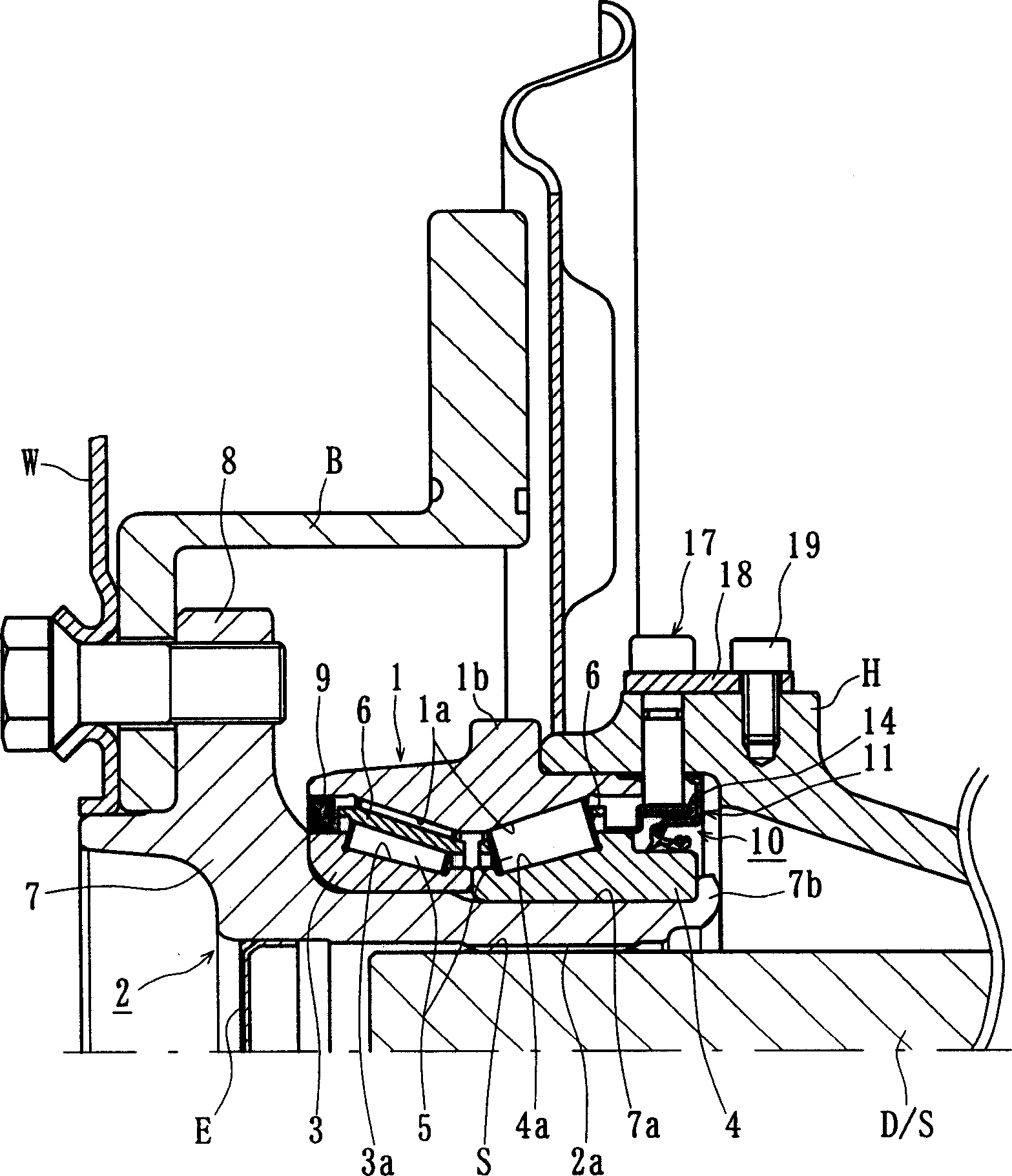
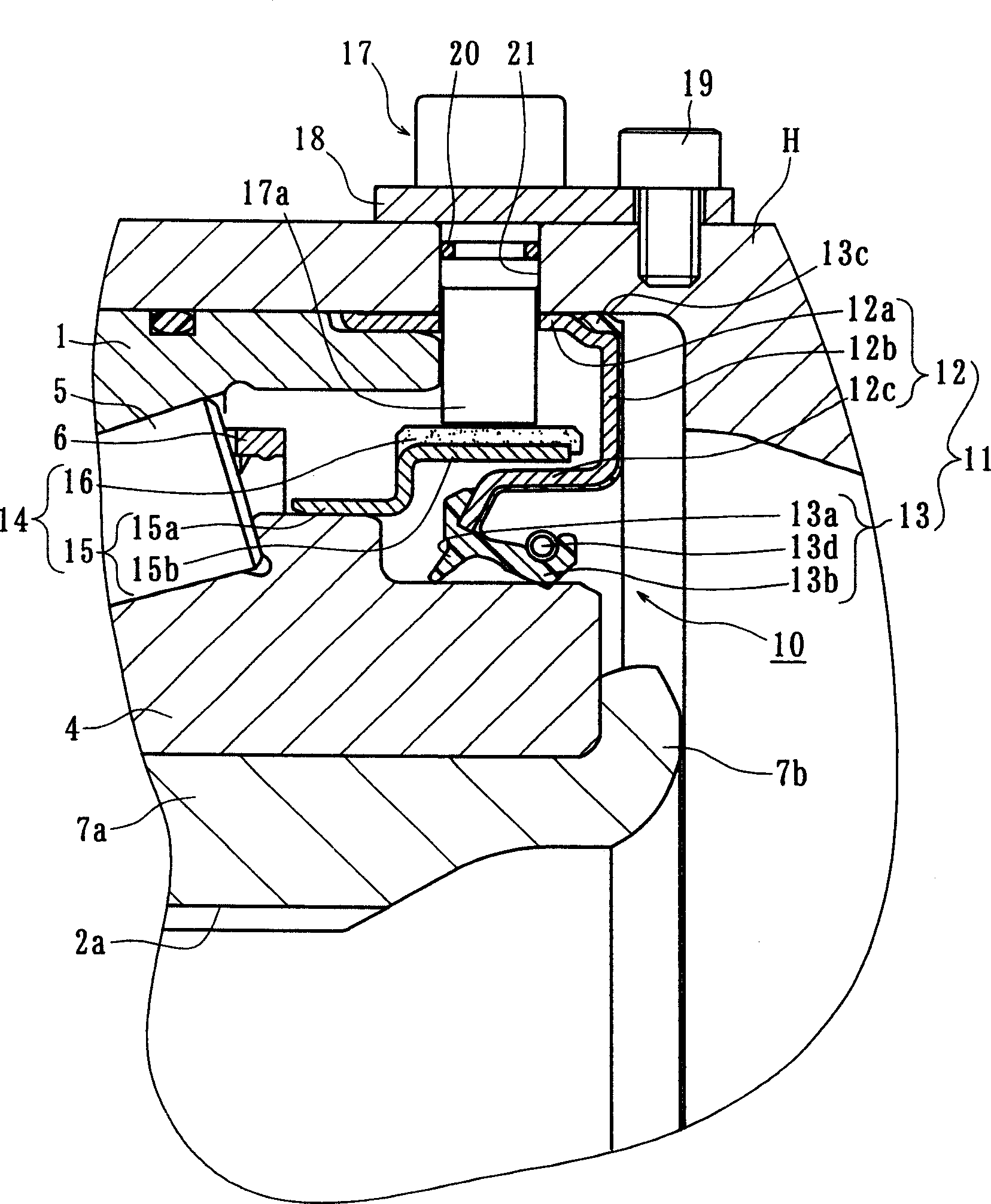
[0026] Hereinafter, embodiments of the present invention will be described in detail with reference to the drawings. figure 1 It is a longitudinal sectional view showing the first embodiment of the semi-floating wheel bearing device of the present invention, figure 2 Yes figure 1Enlarged view of important parts of . In the following description, the side closer to the vehicle outer side in the assembled state of the vehicle is referred to as the vehicle outer side (left side in the drawing), and the side closer to the center is called the vehicle inner side (right side in the drawing).

[0027] In the rolling bearing for a wheel of the present invention, a semi-floating drive shaft D / S is rotatably supported inside a housing (semi-shaft casing) H supported by springs under the chassis of an automobile body. That is, in the semi-floating type wheel bearing device having the wheel rolling bearing of the present invention, one end of the hub H is engaged with an unillustrate...


PUM


Abstract

A vehicle wheel rolling bearing has a sealing device integrated with a magnetic encoder. A semi-float type bearing apparatus has said rolling bearing which can protect a magnetic encoder and improve the sensing ability of the detecting sensor. The rolling bearing has an inner member with a wheel hub having a wheel mounting flange and an inner ring formed with inner raceway surfaces. An outer member is formed with double row outer raceway surfaces opposite the inner raceway surfaces. Double row rolling elements are between the raceway surfaces. Sealing devices include an inboard sealing device with an annular seal fitted on the outer member. A pulsar ring is mounted on the inner member and has an encoder mounted on a cylindrical holding portion. The encoder is arranged opposite to the annular seal. The encoder includes magnetic poles formed by magnetic powder with alternating polarity along its circumferential direction. A detecting sensor passes through the cylindrical portion of the seal and opposes the encoder. A predetermined air gap is kept between the encoder and detecting sensor.

Description

technical field [0001] The present invention relates to a rolling bearing for a wheel which supports a wheel of an automobile etc. so as to freely rotate relative to the body of the vehicle, and more particularly to a rolling bearing for a wheel having a sealing device with a magnetic encoder for detecting rotation speed and a semi-floating bearing using the rolling bearing Bearing device for wheels. Background technique [0002] Conventionally known rolling bearings for wheels include a sealing device with a magnetic encoder for detecting the rotational speed of the wheel, and a sealing device with a magnetic encoder in which the magnetic encoder and the sealing device are integrated. [0003] Rolling bearings for the wheels such as Figure 4 As shown, there are first and second annular sealing plates 62, 63 installed on the inner ring 60 and the outer ring 61, respectively. These sealing plates 62, 63 are respectively comprised from cylindrical part 62a, 63a, and upright ...

Claims


Application Information

Patent Timeline
Patent Type & Authority Applications(China)
IPC IPC(8): B60B35/18F16C19/18F16C19/38F16C19/52F16C33/78F16C41/00G01P3/44
CPCF16C19/386F16C33/7813F16J15/326F16C2326/02F16C41/007G01P3/443
Inventor 乘松孝幸村中章宏
Owner NTN CORP
Why Eureka
Try Eureka