Unlock instant, AI-driven research and patent intelligence for your innovation.

Improved cathode ray tube

A cathode ray tube, transmittance technology, applied in the direction of cathode ray tube/electron beam tube, cathode ray/electron beam tube shell/container, discharge tube, etc., can solve thermal conductivity damage, brightness reduction, color purity reduction, etc. question

Inactive Publication Date: 2005-02-02
LG PHILIPS DISPLAY KOREA CO LTD
View PDF0 Cites 0 Cited by
  • Summary
  • Abstract
  • Description
  • Claims
  • Application Information

AI Technical Summary

Problems solved by technology

[0013] refer to Figure 5 , unlike the panel 1a whose outer surface and inner surface respectively have a specific radius of curvature, the panel 1b whose outer surface is substantially flat and whose inner surface has a specific radius of curvature is from the seal edge line to the mold match line ) has a greater distance, is relatively thicker and heavier, and is therefore more expensive to produce
[0014] In addition, when the panel 1 becomes thicker, damage often occurs inside the furnace due to the difference in thermal conductivity, and the brightness also decreases
[0015] In an attempt to compensate for this reduction in brightness, some manufacturers have tried to increase the width of the phosphor, however, this just creates another problem, that is, in order to increase the width of the phosphor, it is necessary to reduce the (dichroic) black background resolution phosphor. width, but in this case the color purity will be reduced

Method used


Image

  • Improved cathode ray tube
  • Improved cathode ray tube
  • Improved cathode ray tube

Examples


Embodiment Construction

[0033] Hereinafter, a cathode ray tube according to a preferred embodiment of the present invention will be described in detail with reference to the accompanying drawings.

[0034] The cathode ray tube of the present invention includes: a panel having an outer edge portion located at the outer peripheral portion of the panel and extending almost vertically along the inner surface and the outer surface of the panel, wherein the outer surface of the panel is substantially straight and the inner surface It has a specific radius of curvature, a funnel combined with the panel, a fluorescent film is formed on the inner surface of the panel, an electron gun for emitting electron beams, a deflection coil for deflecting electron beams, a A shadow mask of optional function and a reinforcement tape mounted on the peripheral portion of the panel to relieve the pressure generated by the atmosphere.

[0035] Figure 6 Shown is a faceplate of a cathode ray tube according to the invention, ...


PUM

PropertyMeasurementUnit
Diagonal lengthaaaaaaaaaa
Thicknessaaaaaaaaaa
Thicknessaaaaaaaaaa

Abstract

A cathode ray tube comprises a panel of which outer surface is substantially flat and inner surface has a designated radius of curvature, a shadow mask coupled to the panel, the shadow mask having electron beam passing holes, and a reinforcing band mounted on the outer surface of the panel, wherein a diagonal size of an effective surface of the panel is in the range of 397-463 mm, and a thickness of a diagonal end of the effective surface of the panel is in the range of 20-23 mm.

Description

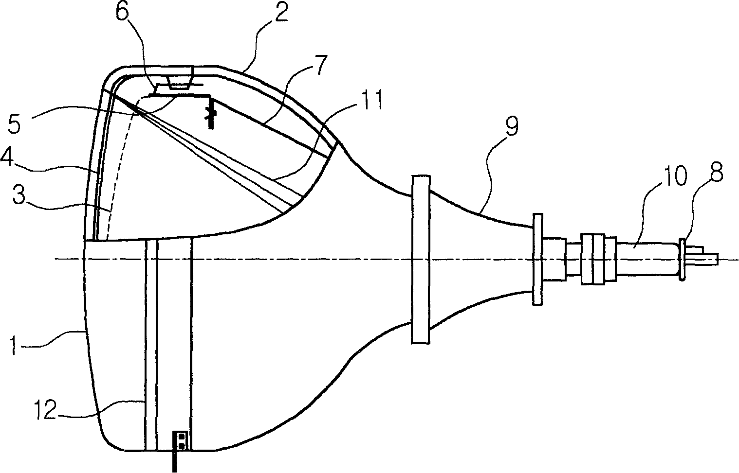
technical field [0001] The present invention relates generally to a cathode ray tube, and more particularly to a cathode ray tube having an improved panel structure whereby damage caused by heat treatment processes can be minimized and the overall weight and production of the panel can be reduced cost. Background technique [0002] figure 1 The structure of a prior art cathode ray tube is shown. [0003] refer to figure 1 , the cathode ray tube includes a panel 1 with a fluorescent film 4 formed on the inner surface, a funnel 2 connected to the panel 1, a shadow mask 3 with a color selection function arranged at a specified distance from the fluorescent film 4, and a support for supporting A shadow mask frame 5 of the shadow mask 3 , an electron gun 8 for emitting electron beams 11 and a deflection coil 9 for deflecting the electron beams 11 are installed on the neck 10 of the funnel 2 . [0004] In particular, the shadow mask frame 5 is combined with the panel 1 through...

Claims


Application Information

Patent Timeline
IPC IPC(8): H01J29/02H01J29/86
CPCH01J29/861H01J2229/8616H01J29/02
Inventor 金警来崔容薰
Owner LG PHILIPS DISPLAY KOREA CO LTD