Moving image decoding apparatus and moving image decoding method

A technology for moving images and decoding devices, applied in image communication, television, electrical components, etc., can solve problems such as deviation in quantization parameter settings, large image quality degradation, and subjective image quality degradation.

Inactive Publication Date: 2005-02-02
PANASONIC CORP
View PDF2 Cites 12 Cited by
  • Summary
  • Abstract
  • Description
  • Claims
  • Application Information

AI Technical Summary

Problems solved by technology

[0011] However, when decoding priority-encoded data in which an important area of ​​a moving image is encoded with priority using a layered encoding scheme, there is a problem if post-filter on / off control is performed based on a quantization parameter, that is, unlike the The image quality of the decoded image of the important area is significantly lower than that of the surrounding area, and the subjective image quality is reduced
[0012] That is, when encoding is performed based on priority from the important area by internally dividing a moving image into an area important to the user and other peripheral areas and setting DCT coefficients of adaptive displacement, the difference between the important area and the peripheral area There will be a deviation in the quantization parameter setting between, the large deviation in the image quality appears in the moving image, and for the surrounding area that is not coded according to the priority, the image quality will drop greatly. Coefficients and quantization parameters are set to apply post-filter filtering processing, although the noise of the entire image can be reduced, but the resolution of the image in the priority coding area is lost

Method used


Image

  • Moving image decoding apparatus and moving image decoding method
  • Moving image decoding apparatus and moving image decoding method
  • Moving image decoding apparatus and moving image decoding method

Examples


Embodiment 1

[0044] In this embodiment, a video decoding device is described that applies a moving picture decoding scheme whereby a value for The filter parameters that control the strength of the noise removal of the post-filter, used when post-filtering the decoded image itself on a single-cell basis, are adaptively controlled and can improve the subjective image quality of the entire screen. When the post-filtering processing of the decoded image is performed based on a single cell, the used filtering parameters can be adaptively controlled, improving the subjective image quality of the full screen.

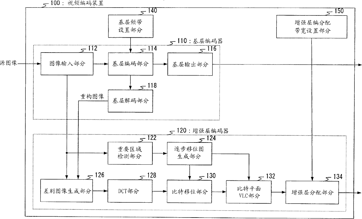
[0045] FIG. 1 is a block diagram showing the structure of a video coding apparatus using a moving image coding scheme according to Embodiment 1 of the present invention.

[0046] The video encoding apparatus 100 shown in FIG. 1 has a base layer encoder 110 for generating a base layer, an enhancement layer encoder 120 for generating an enhancement layer, a base layer band setting section 1...

Embodiment 2

[0078] In this embodiment, a video decoding apparatus is described which uses a moving picture decoding scheme whereby the shift value established when encoding is performed on a single cell basis and the value accepted by each of these cells The filtering parameters used to control the post-filtering noise removal strength are calculated on the basis of the number of bits, and the filtering parameters used when performing the post-filtering processing of the decoded image on a single-cell basis are adaptively controlled, and the entire screen can be improved subjective image quality.

[0079] In Embodiment 2, the coded image is decoded. The coded image is based on a single cell based on a stepwise shift map generated in the video coding device 100 shown in FIG. 1 . Obtained by encoding the shift value inside the screen.

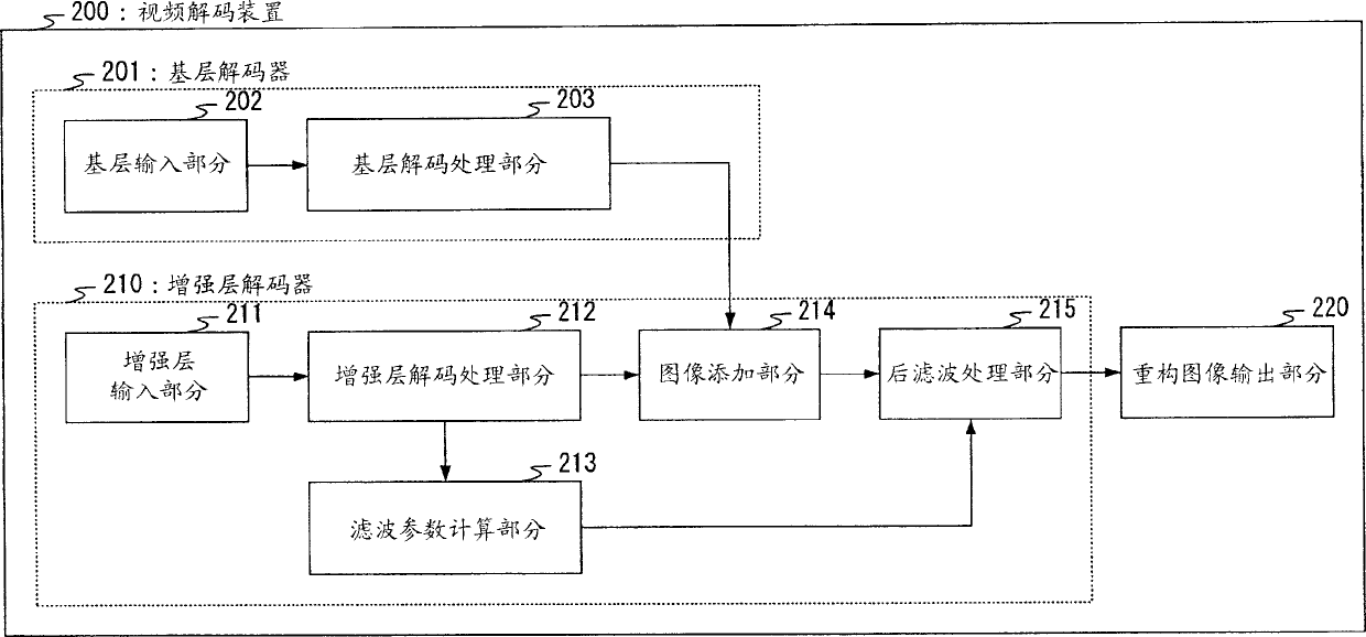
[0080] FIG. 6 is a block diagram showing the structure of a video decoding apparatus using a moving image decoding scheme according to Embodiment 2 of the ...

Embodiment 3

[0110] In this embodiment, a video decoding apparatus is described that employs a moving image decoding scheme whereby, when encoding is performed on a single cell basis, a portion thereof having a large noise cancellation strength with respect to surrounding cells On the basis of the established shift value, the filtering parameters used to control the post-filtering noise removal strength are calculated on the basis of a single cell. When the post-filtering processing of the decoded image is performed based on a single cell, the filtering parameters used can be adaptively controlled. And improve the subjective image quality of the full screen.

[0111] In Embodiment 3, a coded image is decoded by means of a step-by-step shift map generated based on important region information in the video coding device 100 shown in FIG. obtained by encoding inside the screen of .

[0112] FIG. 10 is a block diagram showing the structure of a video decoding apparatus using a moving image de...


PUM


Abstract

A video decoding apparatus that adaptively controls post-filter filter parameters according to a characteristic quantity of priority-coded data priority-coded for individual areas classified by importance within a moving image, and improves the subjective image quality of an overall screen. In a video decoding apparatus 200, a filter parameter calculation section 213 calculates filter parameters that control the noise elimination intensity of a post-filter processing section 215 based on shift values of individual small areas set in a stepwise shift map in which the shift value decreases stepwise from an important area to the peripheral area within a screen in the video coding apparatus, and a post-filter processing section 215 performs post-filter processing of a reconstructed image by applying the calculated filter parameters.

Description

technical field [0001] The present invention relates to a moving picture decoding device and a moving picture decoding method whereby data encoded by priority is decoded on a region basis according to importance. Background technique [0002] The video data transmitted in the traditional video data transmission system is usually compressed in a certain frequency band or less by means of the H.261 scheme, that is, the MPEG (Moving Picture Experts Group) scheme or similar schemes, so that it can be Once the video data is encoded, its video quality will not change even if the transmission frequency band is changed. [0003] However, with the diversification of networks in recent years, fluctuations in frequency bands of transmission paths have increased, and thus video data that allows video transmission whose quality matches a plurality of frequency bands is required. In response to this need, a hierarchical coding scheme having a hierarchical structure and capable of handlin...

Claims


Application Information

Patent Timeline
Patent Type & Authority Applications(China)
IPC IPC(8): H04N19/50H04N19/117H04N19/134H04N19/149H04N19/167H04N19/189H04N19/196H04N19/30H04N19/34H04N19/36H04N19/44H04N19/503H04N19/513H04N19/61H04N19/625H04N19/80H04N19/85H04N19/91
CPCH04N19/00533H04N19/00248H04N19/00593H04N19/0026H04N19/00066H04N19/00424H04N7/26351H04N19/527H04N19/117H04N19/167H04N19/17H04N19/30H04N19/44
Inventor 本田义雄上野山努
Owner PANASONIC CORP
Why Eureka
Try Eureka