Amplifier and the method thereof

A technology of amplifier and signal, applied in the field of high-speed communication, to achieve the effect of reducing noise components

Active Publication Date: 2009-07-01
MEDIATEK INC
View PDF0 Cites 5 Cited by
  • Summary
  • Abstract
  • Description
  • Claims
  • Application Information

AI Technical Summary

Problems solved by technology

But both technologies suffer from transistor channel thermal noise, which dominates the noise of the LNA device

Method used


Image

  • Amplifier and the method thereof
  • Amplifier and the method thereof
  • Amplifier and the method thereof

Examples


Embodiment Construction

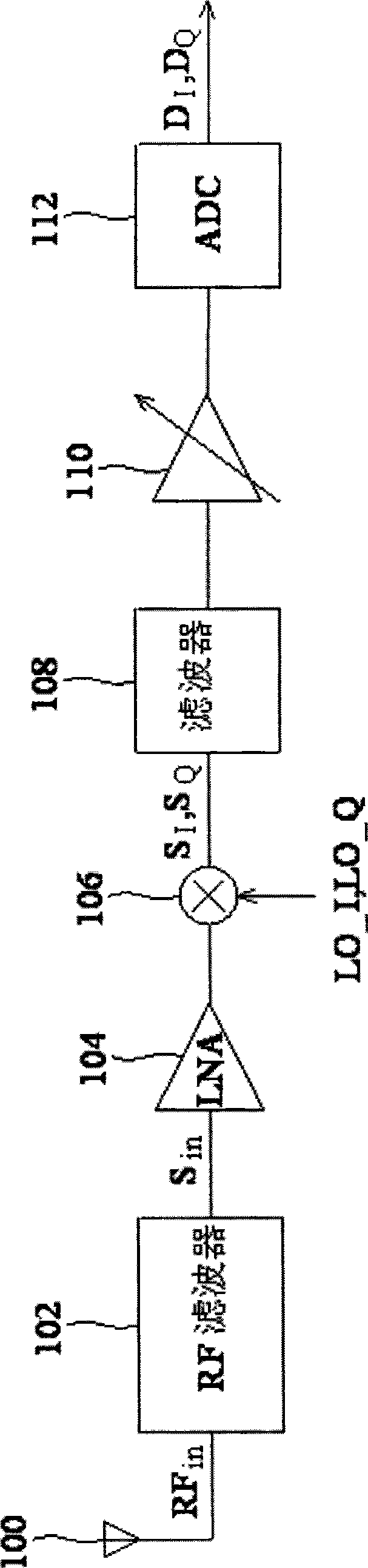
[0018] figure 1 is a block diagram of a direct conversion receiver according to an embodiment of the present invention. The direct conversion receiver includes an antenna 100 , an RF filter 102 , an LNA 104 , a mixer 106 , a filter 108 , an amplifier 110 and an analog-to-digital converter (abbreviated as ADC hereinafter) 112 . Antenna 100 is coupled to RF filter 102 , LNA 104 , mixer 106 , filter 108 , amplifier 110 and ADC 112 .

[0019] The antenna 100 receives the input signal RF in , the input signal RF in After being filtered by the RF filter 102, the out-of-band signals are removed, then amplified by the LNA 104, and then modulated by the local oscillation signals (local oscillation signals) LO_I and LO_Q in the mixer 106 to generate in-phase and quadrature outputs Signal S I and S Q , in-phase and quadrature output signal S I and S Q Filtered by filter 108 in sequence, amplified by amplifier 110, and converted by ADC 112 to generate digital data D I and D Q , t...


PUM


Abstract

The invention relates to an amplifier for amplifying an input signal to generate an output current, comprising an impedance matching network for receiving the input signal to perform impedance matching; a first resistor for receiving the input signal to generate the matched signal; a first transistor having a channel thermal noise to establish a first noise voltage; a second resistor for receiving the channel thermal noise to establish a second noise voltage; and a transconductance circuit, comprising a first transconductance circuit which has a first transconductance coefficient and receives the first noise voltage to generate a first noise current; a second transconductance circuit which has a second transconductance coefficient and receives the second noise voltage to generate a second noise current such that the first and the second noise currents are counteracted with each other to reduce the noises in the output current. In contrast to the prior art, the invention can efficiently reduce the noises in the output current.

Description

technical field [0001] The present invention relates to high-speed communication, in particular to amplifiers and methods for high-speed communication. Background technique [0002] In recent years, the demand for high-speed communication systems has been high. Amplifiers in high-speed communication systems need to meet stringent requirements, such as wideband input matching, high gain, wide bandwidth, and low noise. In addition, because it is more inclined to use complementary metal oxide semiconductor (hereinafter referred to as CMOS) technology to realize the amplifier to obtain a higher degree of integration, the poor radio frequency of CMOS (hereinafter referred to as CMOS) will be encountered when designing the circuit. RF) characteristics, such as large parasitic capacitance, low transconductance, and low supply voltage. [0003] In a low noise amplifier (LNA) device, the most stringent parameters are noise figure and linearity. The noise level can be defined as 10...

Claims


Application Information

Patent Timeline
Patent Type & Authority Applications(China)
IPC IPC(8): H03F1/26H03F1/56H03H11/28
CPCH03F3/211H03F2203/45318H03F1/56H03F3/45179H03F2203/45481H03F3/193H03F1/26H03F2200/451H03H11/28H03F2200/222H03F2203/45576H03F2203/45601H03F3/45183
Inventor 詹景宏
Owner MEDIATEK INC
Why Eureka
Try Eureka