Hologram recording apparatus, hologram recording method, and hologram recording medium

a technology for recording equipment and holograms, applied in the field of hologram recording, can solve problems such as errors in decoding data, and achieve the effect of reducing noise components while information is being recorded in hologram recording media

Inactive Publication Date: 2006-08-01
SONY CORP
View PDF8 Cites 5 Cited by
  • Summary
  • Abstract
  • Description
  • Claims
  • Application Information

AI Technical Summary

Benefits of technology

[0010]The present invention has been made with a view toward solving the problem described above, and it is an object of the invention to provide a hologram recording apparatus, a hologram recording method and a hologram recording medium that reduce noise components generated from a phase modulation type spatial light modulator, thus permitting higher integrity of data to be achieved.

Problems solved by technology

Such diversified diffracted light turns into noises when recording data in a hologram recording medium, leading to a possibility of errors in decoding the data.

Method used


Image

  • Hologram recording apparatus, hologram recording method, and hologram recording medium
  • Hologram recording apparatus, hologram recording method, and hologram recording medium
  • Hologram recording apparatus, hologram recording method, and hologram recording medium

Examples


first embodiment

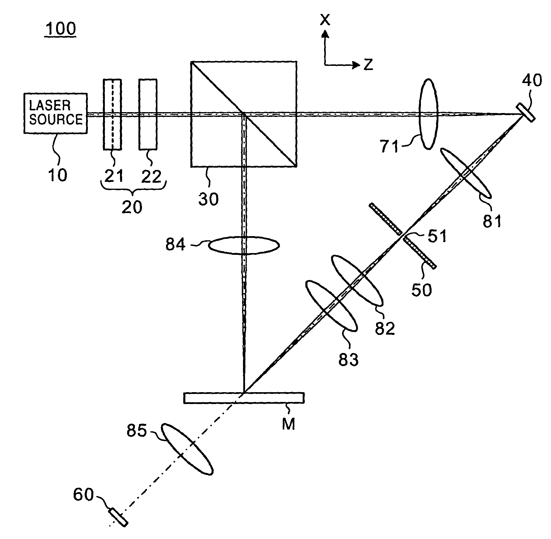
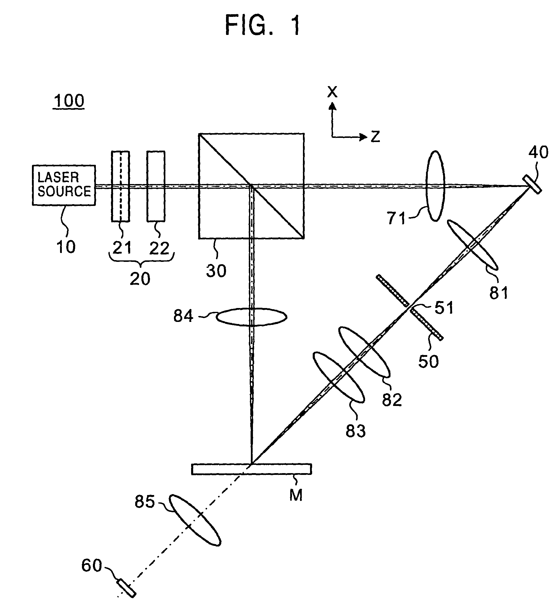
[0066]FIG. 1 is a schematic diagram showing a hologram recording apparatus 100 in accordance with a first embodiment of the present invention. FIG. 2 is a schematic diagram showing the hologram recording apparatus 100 observed from the direction of an X-axis in FIG. 1.

[0067]Referring to FIGS. 1 and 2, the hologram recording apparatus 100 is constructed of a laser source 10, a one-dimensional type beam expander 20, a half mirror 30, a one-dimensional type diffraction control element 40, a slit element 50, a one-dimensional type light receiving element 60, a cylindrical lens 71, and convex lenses 81 through 85 to record and reproduce information in and from a hologram recording medium M.

(Internal Configuration of the One-dimensional Type Diffraction Control Element 40)

[0068]First, the one-dimensional type diffraction control element 40 will be described.

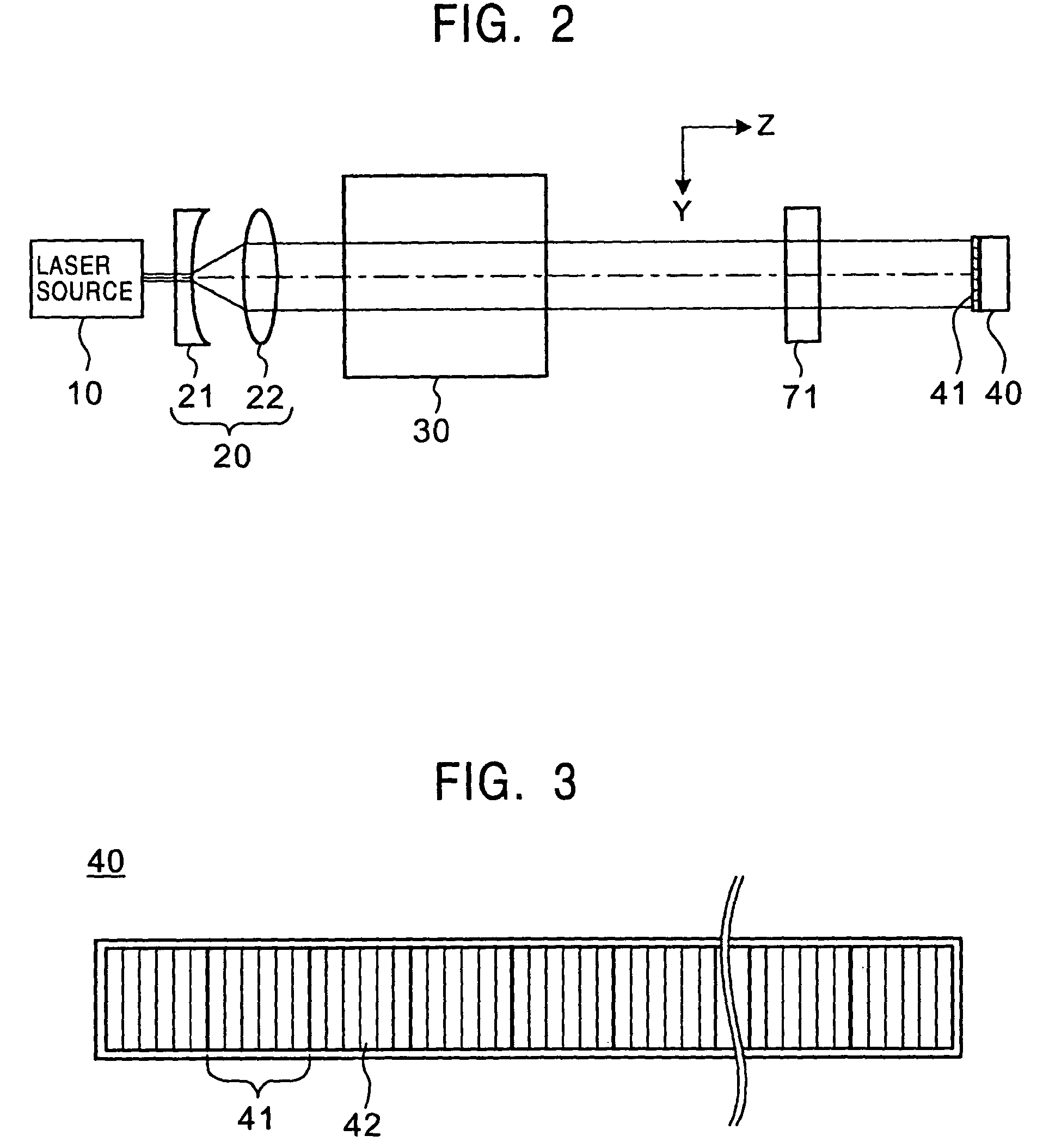
[0069]FIG. 3 is a top plan view of the one-dimensional type diffraction control element 40 observed from above. FIGS. 4 and 5 are a s...

second embodiment

[0146]FIG. 17 is a schematic diagram showing a hologram recording apparatus 200 in accordance with a second embodiment of the present invention.

[0147]Referring to FIG. 17, the hologram recording apparatus 200 is constructed of a laser source 10, a two-dimensional type beam expander 20A, a half mirror 30, a two-dimensional type diffraction control element 40A, a pinhole element 50A, a two-dimensional type light receiving element 60A, a convex lens 71A, and convex lenses 81 through 85 to record and reproduce information in and from a hologram recording medium M.

[0148]Basically, the hologram recording apparatus 200 uses the two-dimensional type diffraction control element 40A in place of the one-dimensional type diffraction control element 40 of the hologram recording apparatus 100. The two-dimensional type diffraction control element 40A has the aforesaid individual diffraction control elements 41 planarly arranged in two directions. This arrangement permits an increased amount of inf...


PUM

PropertyMeasurementUnit
distanceaaaaaaaaaa
electrostatic forceaaaaaaaaaa
refraction indexaaaaaaaaaa

Abstract

A hologram recording apparatus, a hologram recording method and a hologram recording medium reduce noise components generated by a phase modulation type spatial light modulator, thus permitting improved integrity of data to be achieved. A light beam whose diffraction state has been controlled by a diffraction control element is condensed on a hologram recording medium. With this arrangement, a predetermined diffracted light component is removed from a diffracted light beam emergent from the diffraction control element when recording information, which is based on the diffraction state controlled by the diffraction control element, in a hologram recording medium. Thus, noise components when information is recorded can be reduced.

Description

BACKGROUND OF THE INVENTION[0001]1. Field of the Invention[0002]The present invention relates to a hologram recording apparatus for recording data in a hologram recording medium, a hologram recording method and a hologram recording medium.[0003]2. Description of the Related Art[0004]Hologram recording apparatuses for recording data in hologram recording media have been developed.[0005]A hologram recording apparatus is adapted to superimpose signal light modulated by a spatial light modulator on unmodulated reference light on a hologram recording medium to record an obtained interference pattern.[0006]There are two types of spatial light modulators, namely, an intensity type and a phase modulation type. The intensity type spatial light modulator controls the quantity of transmitted or reflected light to perform modulation, and permits use of, for example, a liquid crystal display device.[0007]The phase modulation type spatial light modulator partly changes a light phase to cause inte...

Claims


Application Information

Patent Timeline
Patent Type & Authority Patents(United States)
IPC IPC(8): G03H1/04G03H1/26G03H1/30G11B7/0065G11B7/135
CPCG03H1/02G11B7/1381G11B7/0065G11B7/1353G03H1/0486G03H1/26G03H2001/0204G03H2210/12G03H2225/24G03H2225/32G03H2210/22
Inventor TANAKA, TOMIJISUGIKI, MIKIOISHIOKA, KOJIYAMAZAKI, SHIGERU
Owner SONY CORP
Why Eureka
Try Eureka