Receive coil unit with integrated noise antennas and magnetic resonance imaging system with such a receive coil unit

a technology of receiving coil unit and noise antenna, which is applied in the field of magnetic resonance imaging, can solve the problems of high cost, unusability of mri system, and complex construction of fully equipped magnet rooms, and achieve the effect of reducing noise components and less susceptible to rf nois

Active Publication Date: 2017-10-26
KONINKLJIJKE PHILIPS NV
View PDF2 Cites 4 Cited by
  • Summary
  • Abstract
  • Description
  • Claims
  • Application Information

AI Technical Summary

Benefits of technology

[0005]It is an object of the invention to provide a receive coil unit comprising a receive coil array for use in a magnetic resonance imaging system with multiple antenna units sensitive to magnetic resonance signals, i.e. antenna units sensitive to B-field signals, a magnetic resonance imaging system comprising such a receive coil array and a method for operation of such a magnetic resonance imaging system, which enable a MR signal generation with reduced noise components and to provide an MR system which is less susceptible to RF noise.

Problems solved by technology

A fully equipped magnet room is thus complex to construct and costly.
Without further means omitting the RF-shielding of the examination room renders the MRI system unusable.

Method used


Image

  • Receive coil unit with integrated noise antennas and magnetic resonance imaging system with such a receive coil unit
  • Receive coil unit with integrated noise antennas and magnetic resonance imaging system with such a receive coil unit
  • Receive coil unit with integrated noise antennas and magnetic resonance imaging system with such a receive coil unit

Examples


first embodiment

[0053]The de-noising unit of the first embodiment is adapted to perform de-noising based on antiphase operation to cancel e.g. locally generated interferences. In antiphase operation, an interfering signal is detected and an antiphase signal is generated, whereby the antiphase signal is adjusted in its phase and magnitude, so that it matches the unwanted signal interference in the digital domain, i.e. the locally generated interferences, but it is 180 degrees out of phase, effectively cancelling the interference. In an alternative embodiment, the de-noising unit is adapted to perform de-noising based on an independent component analysis. Independent Component Analysis, also referred to as ICA, is a statistical technique for decomposing a complex dataset into independent sub-parts, which can then be utilized to determine noise compounds of the signal and cancel it by adding an inverted signal of equal amplitude.

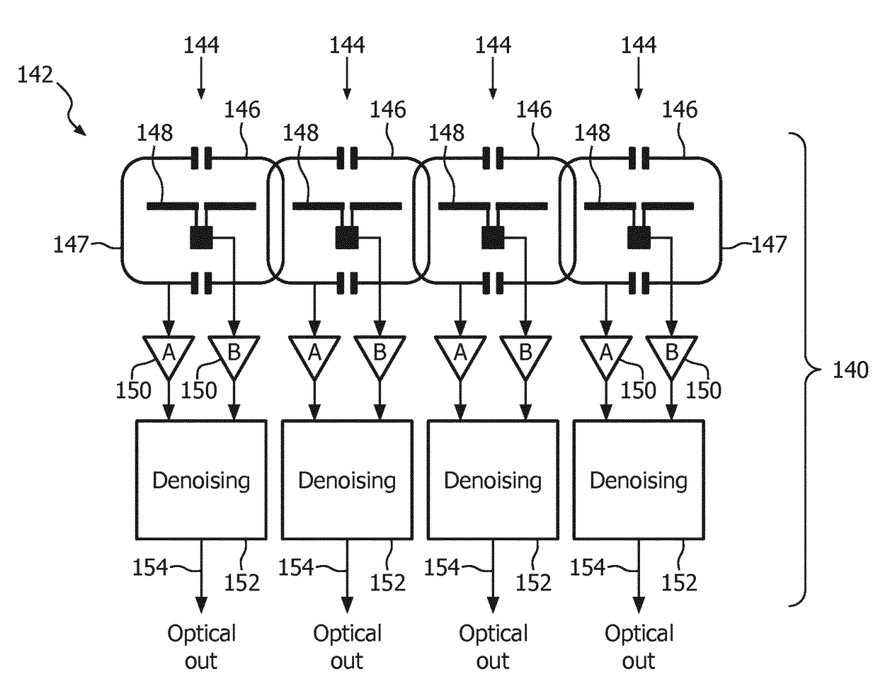
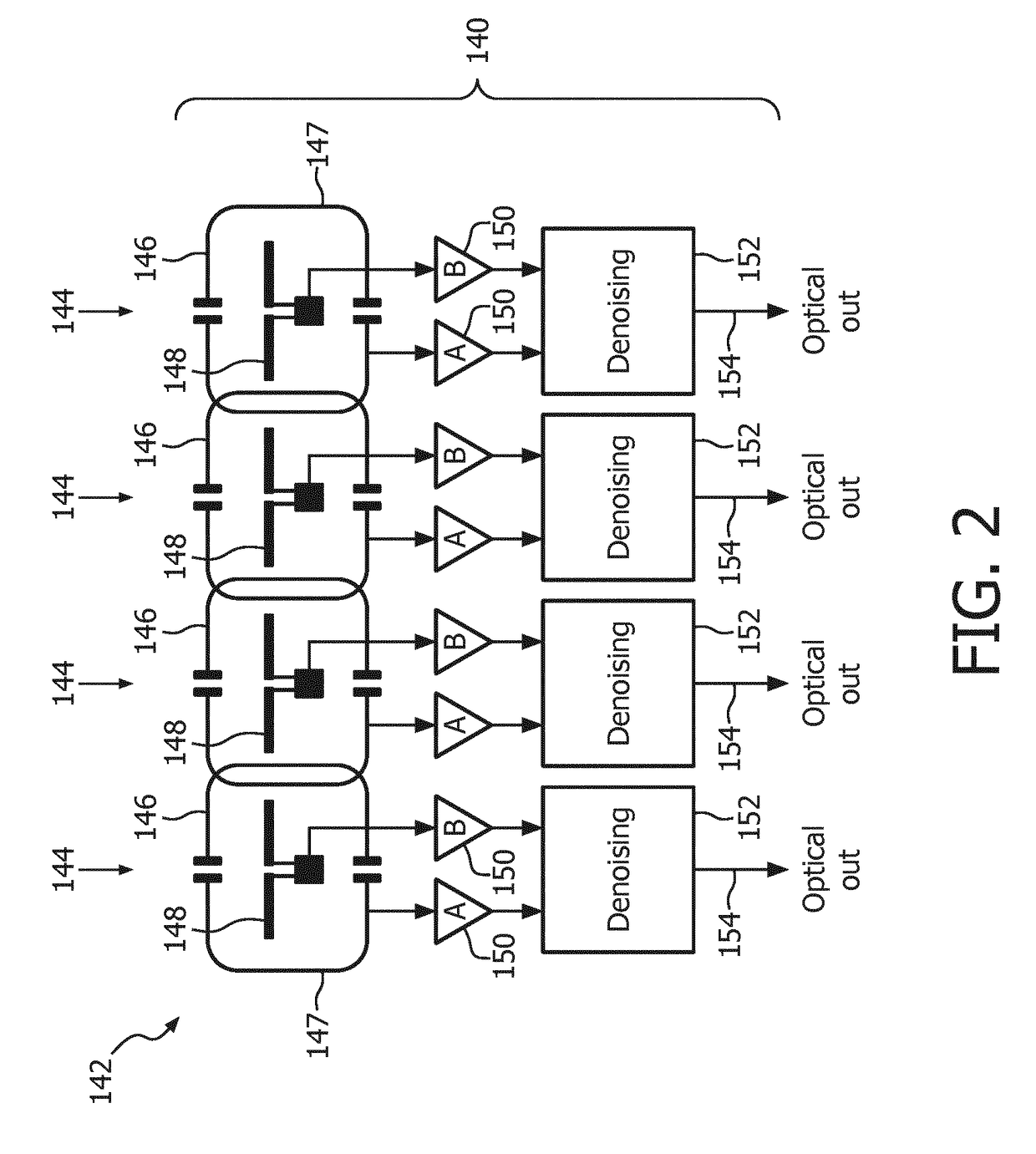
[0054]A receive coil unit 140 according to a second embodiment is shown i...

second embodiment

[0055]The receive coil unit 140 of the second embodiment comprises a receive coil array 142 with multiple antenna units 144. The antenna units 144 each comprise a coil element 146 sensitive to magnetic resonance signals, i.e. B-field signals, and an E-field antenna 148 sensitive to E-field signals. The antenna units 144 further comprise pre-amplifiers 150, which are connected with their inputs to the coil element 146 and the E-field antenna 148. Furthermore, each pre-amplifier 150 is connected to an analog-to-digital converter 156, also referred to as ADC. The ADC 156 comprises a FPGA and performs a conversion of the pre-amplified signals of the coil elements 146 and the E-field antennas 148 into digital signals. Furthermore, the digital signals are provided as optical signals from the ADCs 156.

[0056]According to the second embodiment, the receive coil unit 140 comprises a de-noising unit 152 for filtering noise signals as received from the E-field antennas 148 from the B-field sign...

third embodiment

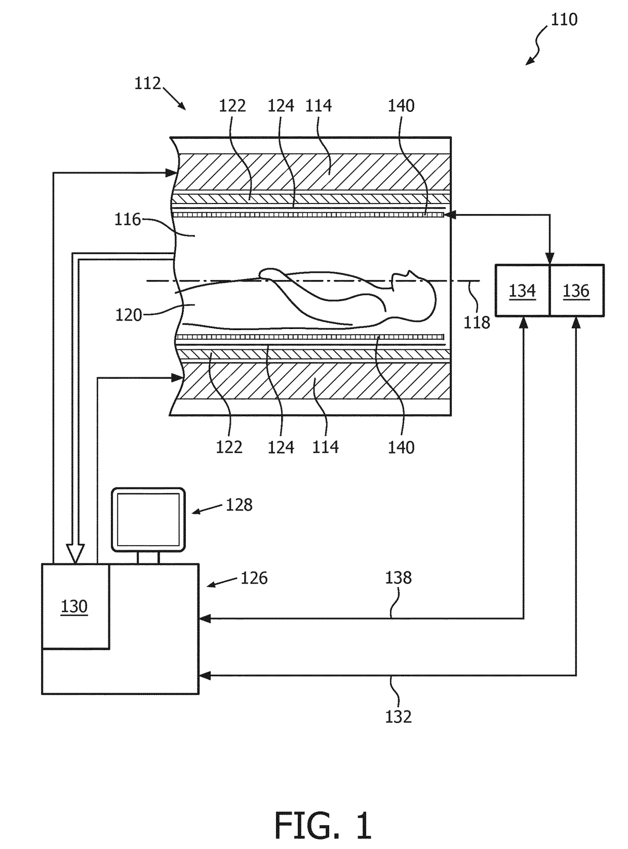
[0059]The receive coil unit 140 of the third embodiment is shown within the examination space 116 of the MR imaging system 110. The examination space 116 is also referred to as bore. The examination space 116 is limited by the main magnet 114 and the magnetic gradient coil system 122.

[0060]The receive coil unit 140 of the third embodiment comprises a receive coil array 142 with multiple antenna units 144. The antenna units 144 each comprise a coil element 146 sensitive to magnetic resonance signals, i.e. B-field signals, and an E-field antenna 148 sensitive to E-field signals. As can be seen in FIG. 4, the receive coil unit 140 comprises a local RF screen 158, and the E-field antennas 148 are connected to the local RF screen 158. In particular, the E-field antennas 148 located in a direction radially outward of the local RF screen 158, whereas the coil elements 146 are located in a direction radially inward of the local RF screen 158. The local RF screen 158 in this embodiment is pr...


PUM


Abstract

The present invention provides a receive coil unit (140) comprising a receive coil array (142) for use in a magnetic resonance imaging system (110) with multiple antenna units (144) sensitive to magnetic resonance signals, i.e. antenna units (144) sensitive to B-field signals, whereby each antenna unit (144) comprises a coil element (146) sensitive to B-field signals, and each antenna unit (144) comprises an E-field antenna (148) sensitive to E-field signals. The present invention also provides a magnetic resonance imaging system (110) comprising a receive coil unit (140) with a receive coil array (142) having multiple antenna units (144) sensitive to magnetic resonance signals, i.e. antenna units (144) sensitive to B-field signals, whereby the receive coil unit (140) is provided as a receive coil unit (140) as specified above. Still further, the present invention provides a method for magnetic resonance imaging comprising the steps of providing a receive coil unit (140) comprising a receive coil array (142) for use in a magnetic resonance imaging system (110) with multiple antenna units (144) sensitive to magnetic resonance signals, i.e. antenna units (144) sensitive to B-field signals, whereby each antenna unit (144) comprises a coil element (146) sensitive to B-field signals, and each antenna unit (144) comprises an E-field antenna (148) sensitive to E-field signals, and performing de-noising of the B-field signals received from the coil elements (146) of the receive coil unit (140) by filtering noise signals, as received from the E-field antenna (148), from the B-field signals.

Description

FIELD OF THE INVENTION[0001]The invention relates to the field of magnetic resonance imaging, in particular to the area of signal processing of magnetic resonance signals, i.e. B-field signals, received from a receive coil unit comprising a receive coil array with multiple antenna units sensitive to magnetic resonance signals.BACKGROUND OF THE INVENTION[0002]In the area of magnetic resonance (MR) imaging and magnetic resonance imaging systems, important improvements have been achieved in the recent years in respect the generation of diagnostic images based on MR imaging.[0003]Nevertheless, to achieve reliable MR image generation, it is important to avoid disturbances of the MR signals received by the used receive coil unit comprising a receive coil array with multiple antenna units sensitive to magnetic resonance signals. Accordingly, in typical MR system setups, the walls of the magnet room have to be lined with RF-shielding metal grids or metal shields. This is predominantly done ...

Claims


Application Information

Patent Timeline
Patent Type & Authority Applications(United States)
IPC IPC(8): G01R33/36G01R33/3415G01R33/422G01R33/565
CPCG01R33/36G01R33/422G01R33/3415G01R33/565G01R33/5659
Inventor LEUSSLER, CHRISTOPHWIRTZ, DANIEL
Owner KONINKLJIJKE PHILIPS NV
Why Eureka
Try Eureka