

Annular-beam coupling system
A technology of annular beam and coupling system, which is applied to the coupling of optical waveguides, optics, light guides, etc., can solve the problems of low resolution, slow image acquisition, and low contrast.
- Summary
- Abstract
- Description
- Claims
- Application Information
AI Technical Summary
Problems solved by technology
Method used
Image

Examples
no. 1 example
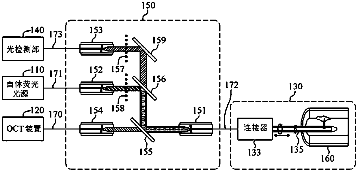
[0051] A ring beam coupling system according to an embodiment of the present invention includes an optical fiber, a collimator, a ring beam generator, and a double-clad fiber.
[0052] The optical fiber transmits the light from the light source, and the collimator receives the light output from the optical fiber and forms a circular parallel beam. The ring beam generator converts the parallel beam into a ring beam, and the ring beam is coupled to the cladding region of the double-clad fiber.
[0053] Fiber corresponds to figure 1 The collimator corresponds to the second collimator 152. and the double-clad fiber corresponds to figure 1 double-clad fiber 172. That is, the ring beam generator of the present invention is located at the output end of the second collimator 152, and converts the parallel beam of the second collimator 152 into a ring beam.
[0054] image 3 is a schematic diagram showing the ring beam coupling system of the first embodiment of the present inventi...
no. 2 example
[0059] Figure 4 is a schematic diagram showing the ring beam coupling system of the second embodiment of the present invention, Figure 5 and Image 6 is a schematic diagram showing an example of a phase spatial filter.
[0060] refer to Figure 4 , the ring beam coupling system can use a phase spatial filter (phase spatial filter) 430 to transform the parallel beam into a ring beam. A phase-spatial filter is an optical filter that changes the phase of light passing through the phase-spatial filter.
[0061] Such as image 3 As shown, the phase spatial filter 430 alters the phase of the collimated beam output from the collimator 320 to transform the collimated beam into an annular beam at the focus position 470 .
[0062] phase spatial filter 430 as Figure 5 As shown, a first protrusion 510 is included. The first protruding portion 510 has a shape protruding toward the traveling direction of the parallel beam 360 or the direction opposite to the traveling direction of...
no. 3 example
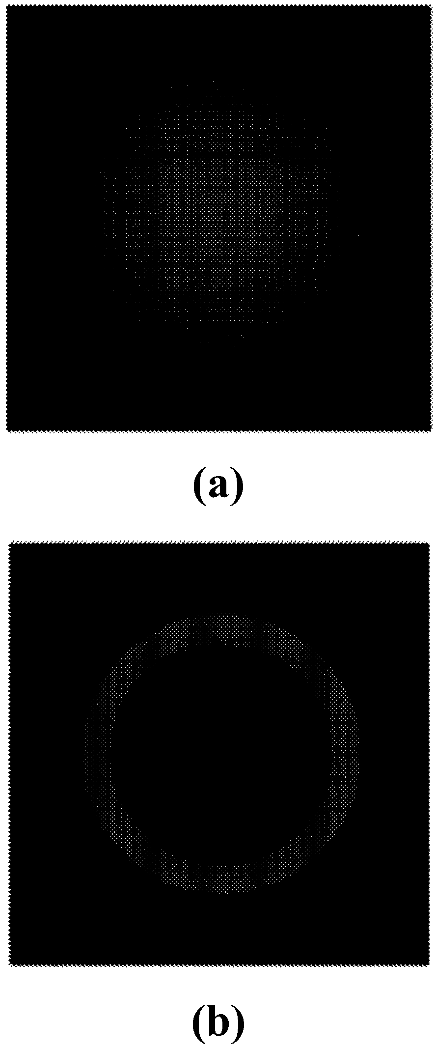
[0070] Figure 7 is a schematic diagram showing a ring-shaped beam coupling system of a third embodiment of the present invention, Figure 8 is displayed Figure 7 Schematic diagram of the annular aperture used in . and Figure 9 is a schematic diagram showing simulation results of a ring beam using a ring filter.
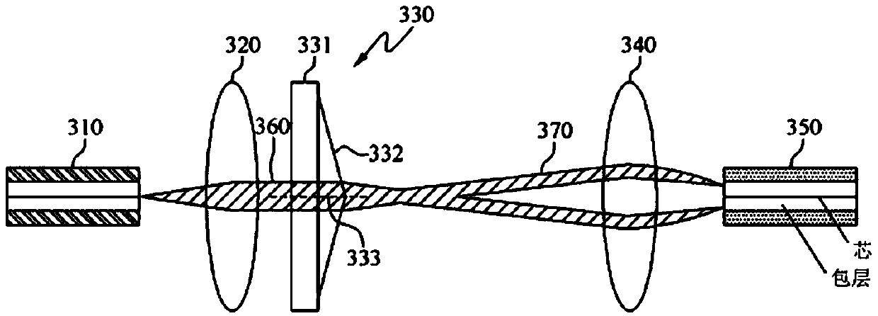
[0071] Such as image 3 As shown, the annular filter 830 transforms the parallel beam output from the collimator 320 into an annular beam.
[0072] The annular filter 830 of the present invention includes a circular light absorbing portion 831 that absorbs a part of the parallel light beam 360 and an annular opening 832 that surrounds the light absorbing portion 831 and allows a part of the parallel light beam 360 to pass through. The light absorbing portion 831 may be made of a substance that absorbs light, and as an example, may contain cobalt.
[0073] The central portion of the parallel beam 360 is blocked by the light absorbing portion 831 , and only the...
PUM
 Abstract
Description
Claims
Application Information