

Lens centering machine
A core-adjusting machine and lens technology, which is applied to the parts of grinding machine tools, machine tools suitable for grinding the edge of workpieces, grinding machines, etc., can solve the problems of larger installation space and inability to carry workpieces, and reduce the installation area of the machine , save the trouble of moving pallets, and increase the installation area
- Summary
- Abstract
- Description
- Claims
- Application Information
AI Technical Summary
Problems solved by technology
Method used
Image

Examples
Embodiment Construction
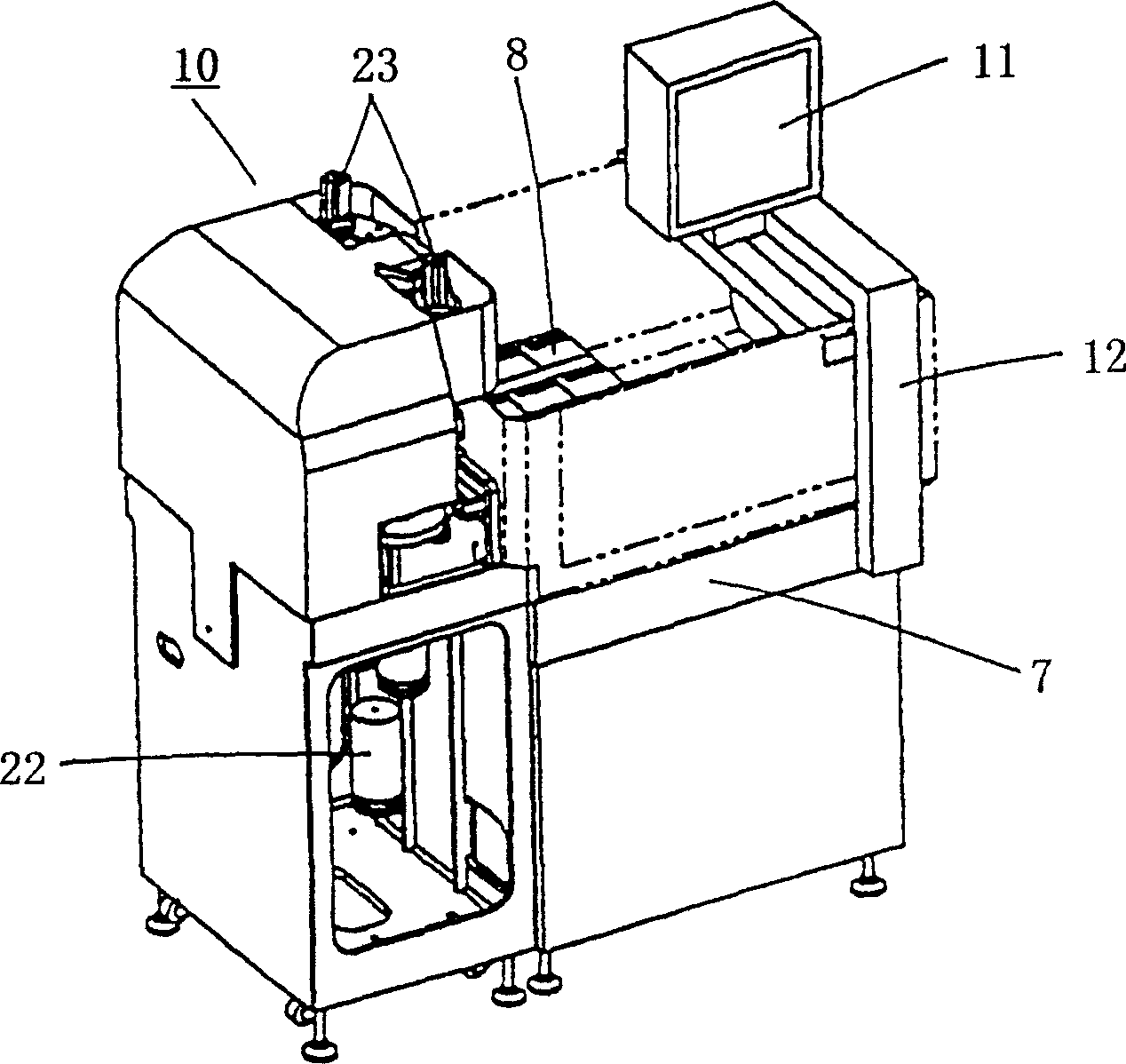
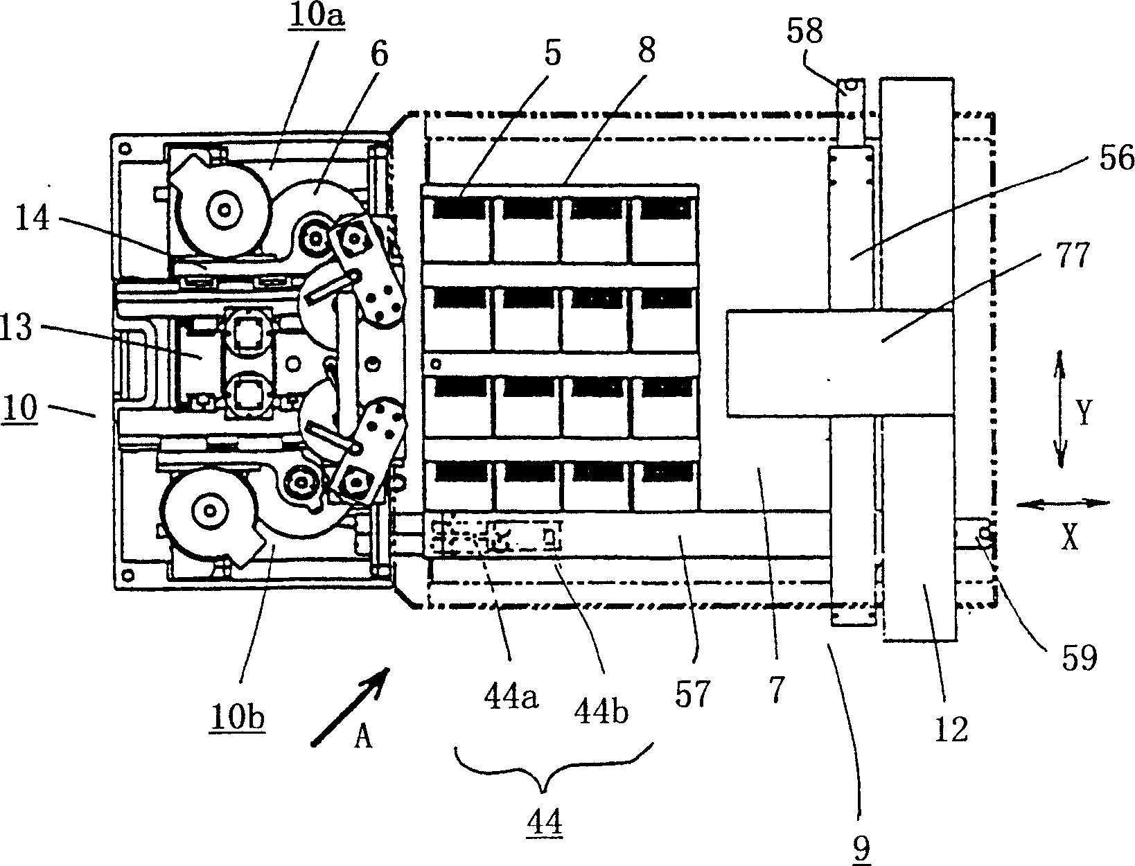
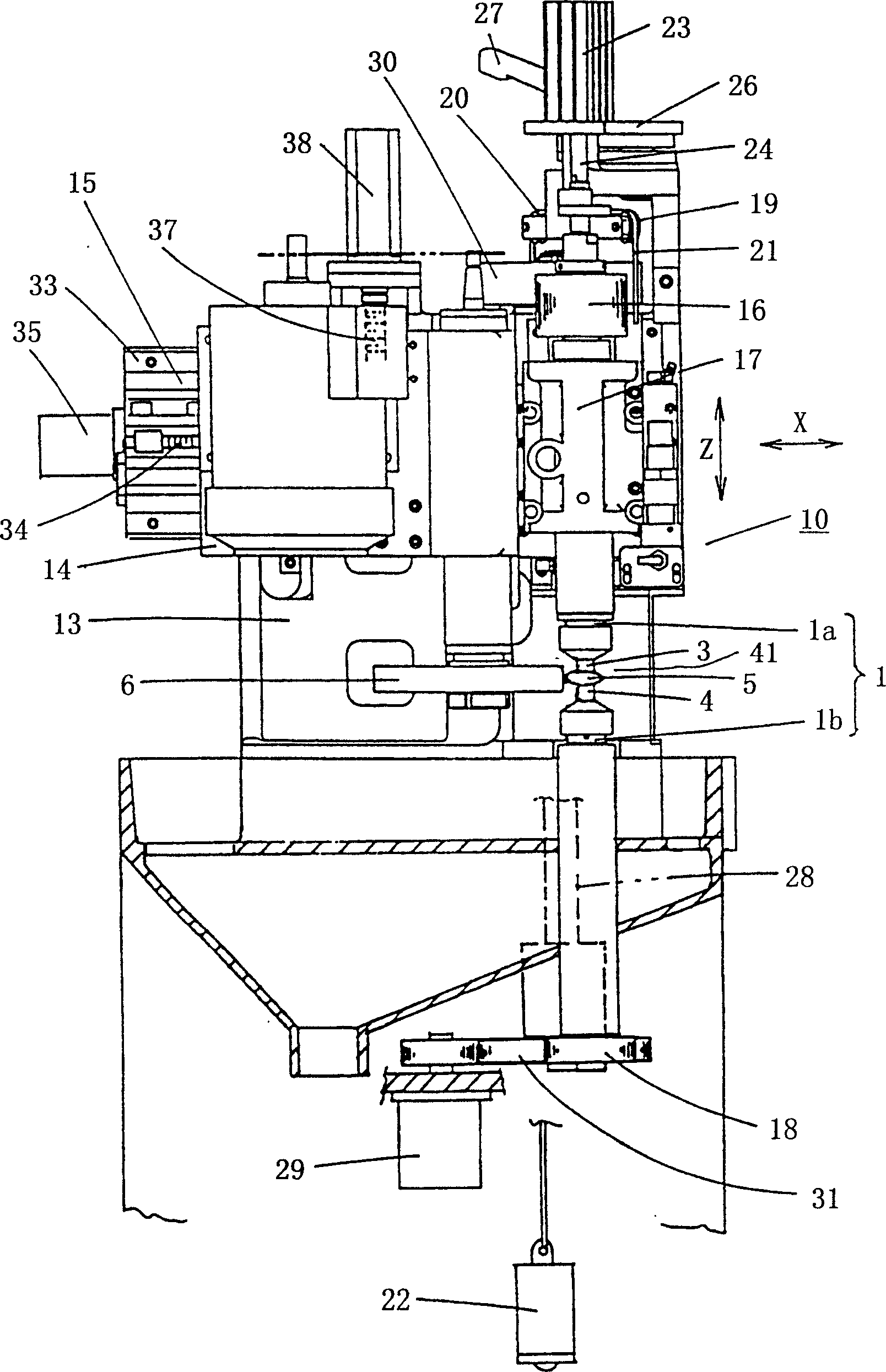
[0044] Hereinafter, embodiments of the present invention will be described with reference to the drawings. figure 1 is from the front left side ( figure 2 Arrow A direction) to see the overall perspective view of the machine of the embodiment device, figure 2 It is a schematic top view of the whole machine, image 3 is the side view of the processing unit, Figure 4 It is the top view of two groups of processing units.
[0045] exist figure 1 , figure 2 Among them, 7 is a work table, 8 is a pallet mounted on the work table 7, and the lenses 5 before and after processing are held on receiving tables provided in matrix on each pallet. 57 is the arm of the loader, which is used by the workpiece table 7 figure 2 The guide beam 56 in the up and down direction (Y direction) guides and runs directly above the workpiece table 7 . On the loader arm 57 there is an edge figure 2 The conveying head 44 that travels in the left and right direction (X direction). On the trans...
PUM
 Abstract
Description
Claims
Application Information