Method for bonding reinforcing plate

A technology of reinforcing plate and hot-pressing combination, which is applied to the improvement of metal adhesion of insulating substrates, secondary treatment of printed circuits, printed circuit components, etc., and can solve the problems that cannot be applied to the bonding method of long strip substrates

Inactive Publication Date: 2005-02-09
SHARP KK
View PDF0 Cites 6 Cited by
  • Summary
  • Abstract
  • Description
  • Claims
  • Application Information

AI Technical Summary

Problems solved by technology

Therefore, the conventional techniques described above cannot satisfy the current situation of handling flexible substrates.
[0020] Even without applying the "reinforcing board bonding method for flexible printed wiring boards" described in the above-mentioned patent publication, the batch method cannot be applied to the bonding method for processing long strip-shaped substrates

Method used


Image

  • Method for bonding reinforcing plate
  • Method for bonding reinforcing plate
  • Method for bonding reinforcing plate

Examples


Embodiment Construction

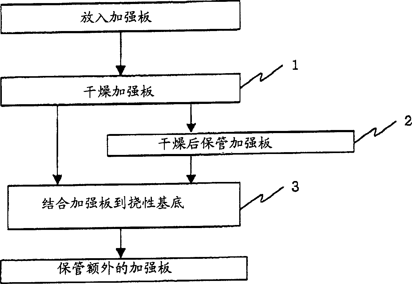
[0032] Drying is preferably carried out in a vacuum cleaner. It is because the above thermocompression bonding and heat treatment can be performed sequentially after the drying treatment.

[0033] Preferably, as the conditions for drying treatment, the vacuum degree of the vacuum chamber in the vacuum defoaming device is 15-75 cmHg (centimeter mercury), the temperature is normal temperature or slightly higher than normal temperature, and the treatment time is 6-18 hours. They are based on good drying results obtained from experiments carried out by the inventors under these conditions.

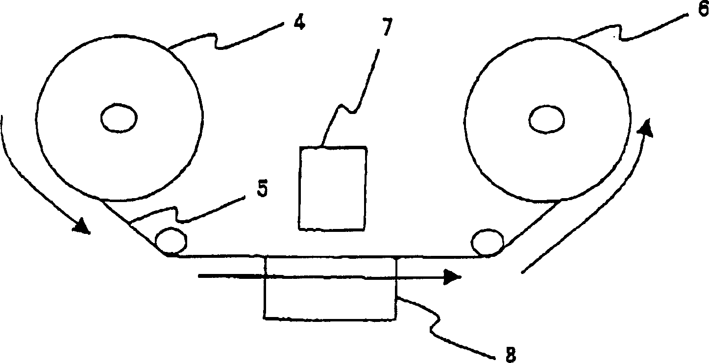
[0034]The above-mentioned thermocompression bonding method is preferably performed by an automatic reinforcement bonding device by continuously transferring a long strip-shaped flexible substrate from a supply reel to a take-up reel by a reel-to-reel method. Perform workpiece processing. It is because the above method is advantageous in terms of mass production.

[0035] Preferably, as the ...


PUM


Abstract

A method for bonding a reinforcing plate to a flexible substrate, the method comprising the steps of: laminating a sheet-shaped thermosetting adhesive on a plate-like polyimide resin to prepare a reinforcing plate; drying the reinforcing plate so that its water content is decreased to the maximum allowable level or less; bonding the reinforcing plate to the flexible substrate through the adhesive by thermocompression bonding; and actually curing the adhesive by heating.

Description

technical field [0001] The present invention relates to a method for bonding a stiffener, and more particularly, to a method for bonding a stiffener to a flexible substrate for a A tape carrier package (TCP) or a chip on FPC (COF), which is one of packages used for various electronic parts such as a cellular phone, a personal digital assistant (PDA) and the like. Background technique [0002] A portable device, such as a cellular phone, a PDA, etc., is ideally made light-weight, thin, short and small, and for the sake of simplicity of its assembly, it is preferable to make the corresponding functional units into components . [0003] For example, a liquid crystal module applied to a cellular phone includes not only a liquid crystal driver mounted in a flexible substrate by forming wiring, but also various elements such as a semiconductor chip of the liquid crystal driver; Some semiconductor chips other than liquid crystal drivers, such as an SRAM and a controller; various ...

Claims


Application Information

Patent Timeline
Patent Type & Authority Applications(China)
IPC IPC(8): H05K1/02H05K1/00H05K3/00H05K3/22H05K3/38
CPCH05K1/0393H05K3/386H05K3/0064H05K2203/1545H05K3/227H05K1/02
Inventor 内藤克幸
Owner SHARP KK
Why Eureka
Try Eureka