
Method of calibrating a component placement machine, device suitable for carrying out such a method, and calibration component suitable for use in such a method or device

A technology of components and machines, applied in the field of devices implementing such a method, calibrating components, which can solve problems such as misplacement of components, mutual position offset, complex calibration methods and devices, etc.

Inactive Publication Date: 2005-02-16
ASSEMBLEON NV
View PDF0 Cites 6 Cited by
  • Summary
  • Abstract
  • Description
  • Claims
  • Application Information

AI Technical Summary

Problems solved by technology

[0005] The methods and devices known per se for the calibration of parts placement machines are relatively complex and time-consuming, with the result that the mutual position of the reference element and the robot is rarely checked
However, if the mutual position is often subject to offset due to wear, temperature fluctuations, etc., this will lead to components being incorrectly placed on the substrate

Method used


Image

  • Method of calibrating a component placement machine, device suitable for carrying out such a method, and calibration component suitable for use in such a method or device
  • Method of calibrating a component placement machine, device suitable for carrying out such a method, and calibration component suitable for use in such a method or device

Examples


Embodiment Construction

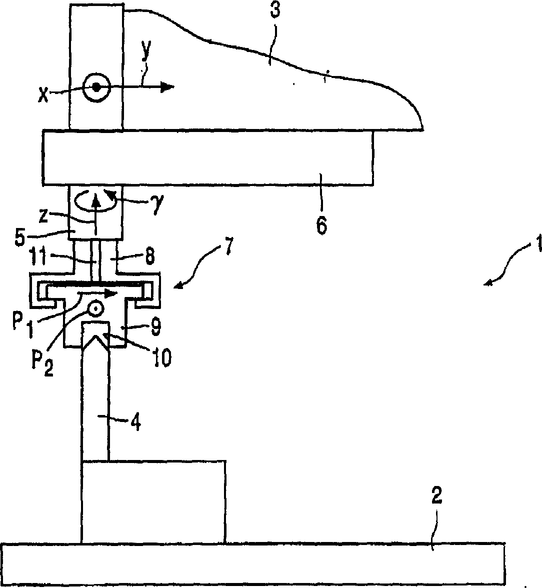
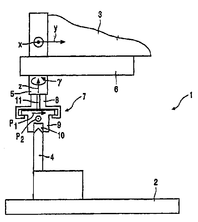
[0022] figure 1 A component placement machine 1 is shown, which is known per se and is provided with a substrate holding device 2 and a robot 3 displaceable relative to the substrate holding device 2, the substrate holding device 2 being provided with a reference element 4, which The reference element 4 comprises at least one pin and is adapted to align a substrate (not shown) with the substrate holder 2 .

[0023] The automatic machine 3 can be displaced in the X and Y directions. The automatic machine 3 is provided with a clamping device 5 that can be displaced in the Z direction relative to the automatic machine 3 and can also rotate in a Φ direction. The automatic machine 3 is further provided with A laser measuring device 6 . Part placement machines as described are known per se until now.

[0024] However, the component placement machine 1 according to the invention further comprises a calibration component 7 having a first part 8 and a second part 9 which can be align...


PUM


Abstract

Method and device for calibrating a component placement machine (1) which comprises a substrate holder (2) having at least one reference element (4) and a robot (3) having a gripper (5). A calibration component (7) is moved to an expected position of the reference element (4) relative to the robot (3) by means of the gripper (5). The calibration component (7) comprises a first part which (8) can be coupled to the gripper (5) in a removable way, and a second part (9) which is movable relative to said first part (8). The calibration component (7) is aligned relative to the reference element (4) by means of said second part (9), during which alignment said second part (9) moves relative to said first part (8). The actual relative position of the reference element (4) relative to the robot (3) is then determined on the basis of said movement.

Description

technical field [0001] The invention relates to a method of calibrating a component placement machine provided with a substrate holding device comprising at least one reference element and a robot comprising a gripping device. [0002] The invention also relates to a device suitable for carrying out such a method. [0003] The invention further relates to a calibration component suitable for use in such a method or such an apparatus. Background technique [0004] In placing components on a substrate supported by a substrate holding device by a component placement machine, it is extremely important to place the components at desired positions on the substrate. For this purpose, for example, by means of holes present in the substrate, the substrate is positioned on a reference element of the substrate holding device comprising pins, which fixes the position of the substrate relative to the reference element, and a part is then clamped by the clamping device Picking, the posi...

Claims


Application Information

Patent Timeline
Patent Type & Authority Applications(China)
IPC IPC(8): B25J9/10B25J9/16B25J9/22H05K13/04
CPCG05B2219/39024B25J9/1692G05B2219/39021H05K13/089
Inventor A·J·P·M·维米尔D·范德文R·库伦M·F·A·雷斯
Owner ASSEMBLEON NV
Learn More