
Electric Motors for High Temperature Applications

A technology of electric motors and high temperature, applied in the field of electric motors, can solve the problems of complex design, manufacturing and expensive operation of electric motors, and achieve the effect of cheap and easy manufacturing

Active Publication Date: 2016-03-16
MAXON MOTOR AG
View PDF5 Cites 0 Cited by
  • Summary
  • Abstract
  • Description
  • Claims
  • Application Information

AI Technical Summary

Problems solved by technology

[0005] Electric motors known from US 6,489,697 B1 have a relatively complex design and are expensive to manufacture and run

Method used


Image

  • Electric Motors for High Temperature Applications

Examples


Embodiment Construction

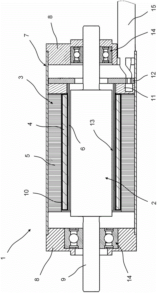
[0022] The electric motor 1 is designed as an inner rotor motor and comprises a rotor 2 and a hollow cylindrical stator 3 which is arranged coaxially with respect to the rotor and surrounds the inner rotor 2 . The inner rotor 2 is not shown in the illustrated section. The exact configuration of the rotor is not shown in further detail. The rotor comprises permanent magnets or a plurality of permanent magnet segments distributed over the circumference. The housing of the electric motor according to the invention, in which all the parts of the electric motor are housed, is indicated by reference number 7 in the figures. The housing 7 consists of a very simple hollow cylindrical sleeve, preferably of steel. A case cover 8 is provided at either end of the case 7 in the axial direction, and the case cover 8 seals the case 7 in the axial direction. Both housing covers 8 contain a ball bearing 14 each for rotatably mounting the shaft 9 of the inner rotor 2 .

[0023] The stator 3...


PUM


Abstract

The electric motor (1) has a rotor (2) and a stator (3) with a hollow-cylindrical, ironless stator winding (4) which is wound from a stoved-enamel wire. The hollow-cylindrically designed stator winding is enclosed by a hollow-cylindrical soft-magnetic return. The stator winding is supported by a hollow-cylindrical supporting sleeve which is laid radially inside against the stator winding. The sleeve is made of ceramic or zirconium oxide.

Description

technical field [0001] The invention relates to an electric motor for high temperature applications according to the preamble of independent claim 1 . This motor includes a rotor and a stator having a hollow cylindrical coreless stator winding made of baked glazed wire and having a soft magnetic circuit surrounding the stator winding. Background technique [0002] Possible applications of such electric motors, which have to withstand high temperatures, can be found, for example, in the fields of aerospace, vehicle and aircraft construction, extraction and processing of raw materials, especially in testing and test drilling for oil and gas in the oil industry and in power plant technology. [0003] In motors known from the prior art for high-temperature applications, the stator windings are not wound onto a slotted laminated core, but are designed as hollow cylindrical coreless stator windings. The stator winding usually consists of several individual diamond windings overla...

Claims


Application Information

Patent Timeline
Patent Type & Authority Patents(China)
IPC IPC(8): H02K1/18
CPCH02K3/47H02K3/30H02K3/44H02K5/128H02K11/0094
Inventor 罗宾·菲利普斯科内利亚·斯图比卡瓦尔特·库恩
Owner MAXON MOTOR AG
Learn More