Vehicle braking system and hydraulic (steam pressure) conducting protector for preventing brake not work

A technology of automobile brakes and protectors, which is applied in the direction of brake safety systems and pipeline layouts, to achieve the effects of avoiding major traffic accidents, convenient installation, and reasonable design

Inactive Publication Date: 2005-02-23
张国良
View PDF2 Cites 1 Cited by
  • Summary
  • Abstract
  • Description
  • Claims
  • Application Information

AI Technical Summary

Problems solved by technology

In the automobile brake system, a hydraulic (air) pressure conduction protector is installed, and the oil (air) circuit from the master cylinder to the front and rear brake hoses and brake cylinders in the brake system is individually controlled. The hydraulic (pneumatic) pressure conduction protector for automobile brake failure has not been reported or practical in practice

Method used


Image

  • Vehicle braking system and hydraulic (steam pressure) conducting protector for preventing brake not work
  • Vehicle braking system and hydraulic (steam pressure) conducting protector for preventing brake not work
  • Vehicle braking system and hydraulic (steam pressure) conducting protector for preventing brake not work

Examples


Embodiment 1

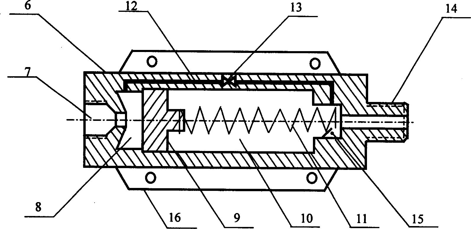
[0020] Example 1: figure 2 A schematic diagram of the structure of the hydraulic conduction protector is provided. It can be seen from the figure that the hydraulic conduction protector is composed of a housing 6, a plunger 9, a spring 11, an emptying auxiliary line 12, and an auxiliary line valve 13. The middle of the housing 6 is empty. The chamber is the main oil circuit. One end of the housing 6 has an oil inlet 7, which is connected to the master pump oil pipeline 5; the other end has an interface 14, which communicates with the oil storage chamber 10 at the rear end of the plunger 9. The interface 14 communicates with the brake hose 3 . The plunger 9 separates the main oil circuit into two oil storage chambers in the middle cavity. Between the front end of the plunger 9 and the oil inlet 7 is an oil storage chamber 8, between the rear end of the plunger 9 and the interface 14 is an oil storage chamber 10, the spring 11 is installed at the rear end of the plunger 9, and...

Embodiment 2

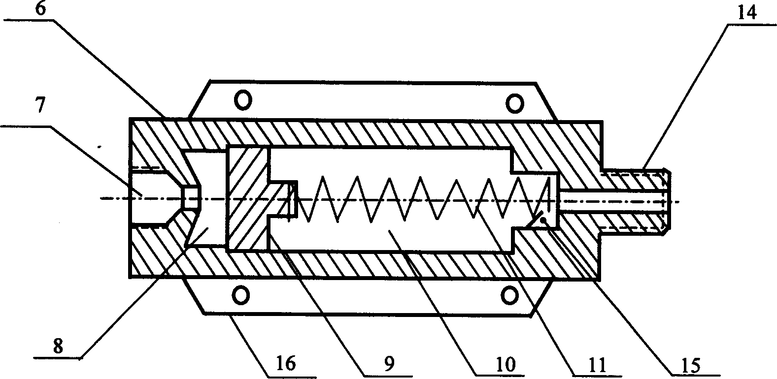
[0021] Example 2: image 3 Provided is a schematic diagram of the structure of the air pressure conduction protector used in the air pressure brake system. The air pressure conduction protector is composed of a housing 6, a plunger 9 and a spring 11. The middle of the housing 6 is a cavity as the main air circuit, and one end has an inlet The air port 7 has an interface 14 at the other end; the plunger 9 divides the main air path into two air storage chambers 8 and 10 in the cavity, and the air storage chamber 8 is between the front end of the plunger 9 and the air inlet 7, Between the rear end of the plunger 9 and the interface 14 is an air storage chamber 10, and the spring 11 is placed in the air storage chamber 10 at the rear end of the plunger 9; the air storage chamber 8 at the front end of the plunger 9 communicates with the master cylinder oil through the air inlet 7 The pipeline 5 and the air storage chamber 10 at the rear end of the plunger 9 are connected to the bra...


PUM


Abstract

A braking system of car features that a hydraulic (or pneumatic) protector is additionally used in the braking system for respectively controlling the front and back flexible braking flexible braking tubes. Said protector has a casing with central cavity as main oil (or air) channel, an oil (or air) inlet connected to oil (or air) trunk,and an interface connected to flexible braking tubes. A plunger in said central cavity divides the main oil (or air) channel into front and back oil (or air) cavities. A spring is arranged in the back oil (or air) cavity.

Description

Technical field: [0001] The invention relates to an automobile brake system and a hydraulic (air) pressure conduction protector for preventing brake failure. Background technique: [0002] There are two types of automobile brakes: oil pressure brakes and steam pressure brakes. Regardless of the type of brake, the brake system is composed of a brake master cylinder, brake sub-cylinder, brake hose, brake pads, etc. The brake master cylinder is connected to the brake hose, The brake hose is connected to the front and rear brake cylinders of the car, and the brake cylinders push the brake pads. When braking, the brake pads hug the wheels of the wheels through the brake oil pressure in the master cylinder, sub cylinders, hoses and pipelines to stop the vehicle. Take hydraulic brakes as an example: When the vehicle is running at high speed on the road, sometimes the brake oil hose will break or the sub-pump will leak. Since there is no device in the brake system that can control...

Claims


Application Information

Patent Timeline
IPC IPC(8): B60T17/04B60T17/22
Inventor 张国良
Owner 张国良
Why Eureka
Try Eureka