Textile machine

A technology of textile machinery and spindle, which is applied in the field of textile machinery, and can solve the problems of larger bending angle, limitation of yarn types, and higher height of machine base, etc., and achieve the effects of restraining tension changes, easy maintenance, and good maintainability

Active Publication Date: 2005-02-23
TMT MACHINERY INC
View PDF3 Cites 2 Cited by
  • Summary
  • Abstract
  • Description
  • Claims
  • Application Information

AI Technical Summary

Problems solved by technology

[0007] (1) There is a silk path at a hidden position behind the winding device. In order to make the yarn pass through the silk path, a special threading device is required, which increases the cost
[0008] (2) Since the traversing device is located in a concealed position behind the winding device, it is difficult to reach in, and the operability of maintenance is poor
[0009] (3) Since the silk path is concealed, it is difficult to find the broken spindle
[0010] (4) Since the bending angle of the yarn path (especially the yarn path from the auxiliary heater to the winding device) becomes larger, the types of yarns that can be processed are limited
[0012] However, in such a false twist processing machine, not only the above-mentioned problem (1) still exists, but also a new problem that the stand height becomes higher

Method used


Image

  • Textile machine
  • Textile machine
  • Textile machine

Examples


Embodiment Construction

[0036] best practice

[0037] The false twist processing machine 1 which is one embodiment of the textile machine of this invention is demonstrated using drawing.

[0038] First, the overall structure of the false twisting machine 1 will be described with reference to the drawings.

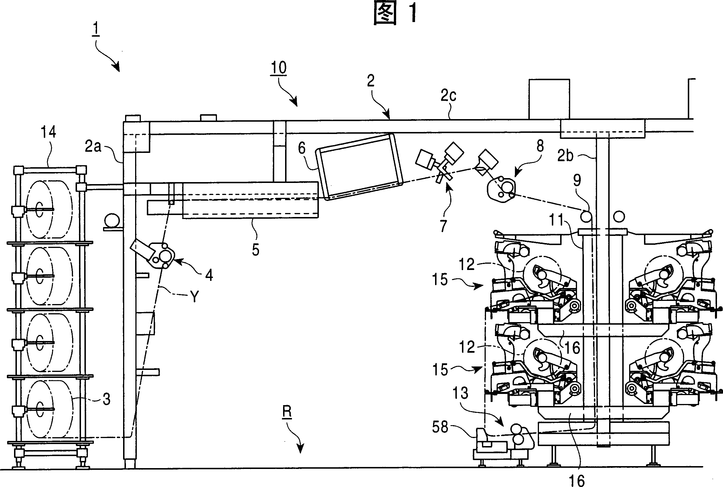
[0039] As shown in FIG. 1 , a false twist processing machine 1 is constituted by a plurality of spindles 10 arranged in parallel in the vertical direction of the drawing, and each spindle 10 is supported by a frame 2 of the false twist processing machine 1 .

[0040] The stand 2 surrounds a working channel R provided along the parallel arrangement direction of the spindles 10 . The stand 2 includes a pair of upright frames 2a, 2b opposed to each other in the horizontal direction across the working passage R, and a connecting frame 2c connecting the upper ends of the upright frames 2a, 2b.

[0041] The spindle 10 is a device that heats a sliver (hereinafter referred to as “yarn”) Y drawn from one...


PUM


Abstract

Provided is a fiber machine capable of eliminating the problems in the conventional technique wherein it requires a yarn threading device to be particularly devoted to thread a thread guide to a hidden position behind each takeup device, the easiness to conduct the maintenance work of its traversing device remains poor, yarn severance weights are difficult to find, and the yarn type to admit processing is restricted owing to the refraction angle of the thread guide. The fiber machine includes a provisionally twining machine 1 arranged so that taking-out of a yarn package 12 from each takeup device 15 and supplying an empty bobbin 21 to the takeup device 15 are conducted from the side with the working passage R, wherein the takeup devices 15 are arranged zigzag along the in-line laid direction of the weights 10 in such a fashion that the takeup devices 15 of adjoining weights 10 are positioned different in the up-and-down positioning, and a guide for yarn running is installed so that each yarn Y led into the takeup device 15 runs outside the space in which taking-out of the produced package 12 out of an other takeup device 15 and supplying a bobbin 21 to other takeup device 15 take place.

Description

technical field [0001] The present invention relates to a technology of a textile machine. The structure of the textile machine is that a plurality of spindles are arranged side by side in one direction, and each spindle is equipped with a winding device, and each winding device is arranged in multiple layers in the vertical direction. One direction side of each winding device performs taking out of a winding package (winding package) from the winding device and supplying an empty bobbin to the winding device. Background technique [0002] In the past, a plurality of spindles were arranged side by side in one direction and a winding device was arranged on each spindle, and each winding device was arranged in multiple layers in the up and down direction. There was a bulk finishing device disclosed in Patent Document 1 (false twist processing machine) or the spinning and bulking processing machine (false twisting processing machine) disclosed in Patent Document 2. [0003] In...

Claims


Application Information

Patent Timeline
Patent Type & Authority Applications(China)
IPC IPC(8): B65H54/28B65H54/22B65H54/70B65H57/06B65H67/04D01H9/02D02G1/04
Inventor 坂本信雄
Owner TMT MACHINERY INC
Why Eureka
Try Eureka