Method of controlling a receiver and a transmitter to handle a transmission window size change procedure

A technology for adjusting programs and receivers, applied in transmission systems, network data management, digital transmission systems, etc., can solve problems such as loss of control signaling, and achieve the effect of improving wireless transmission efficiency

Inactive Publication Date: 2005-02-23
INNOVATIVE SONIC
View PDF0 Cites 2 Cited by
  • Summary
  • Abstract
  • Description
  • Claims
  • Application Information

AI Technical Summary

Problems solved by technology

[0012] The main purpose of the present invention is to provide a method for processing the transmission frame adjustment program to solve the problem caused by the loss of control signaling in wireless transmission

Method used


Image

  • Method of controlling a receiver and a transmitter to handle a transmission window size change procedure
  • Method of controlling a receiver and a transmitter to handle a transmission window size change procedure
  • Method of controlling a receiver and a transmitter to handle a transmission window size change procedure

Examples


Embodiment Construction

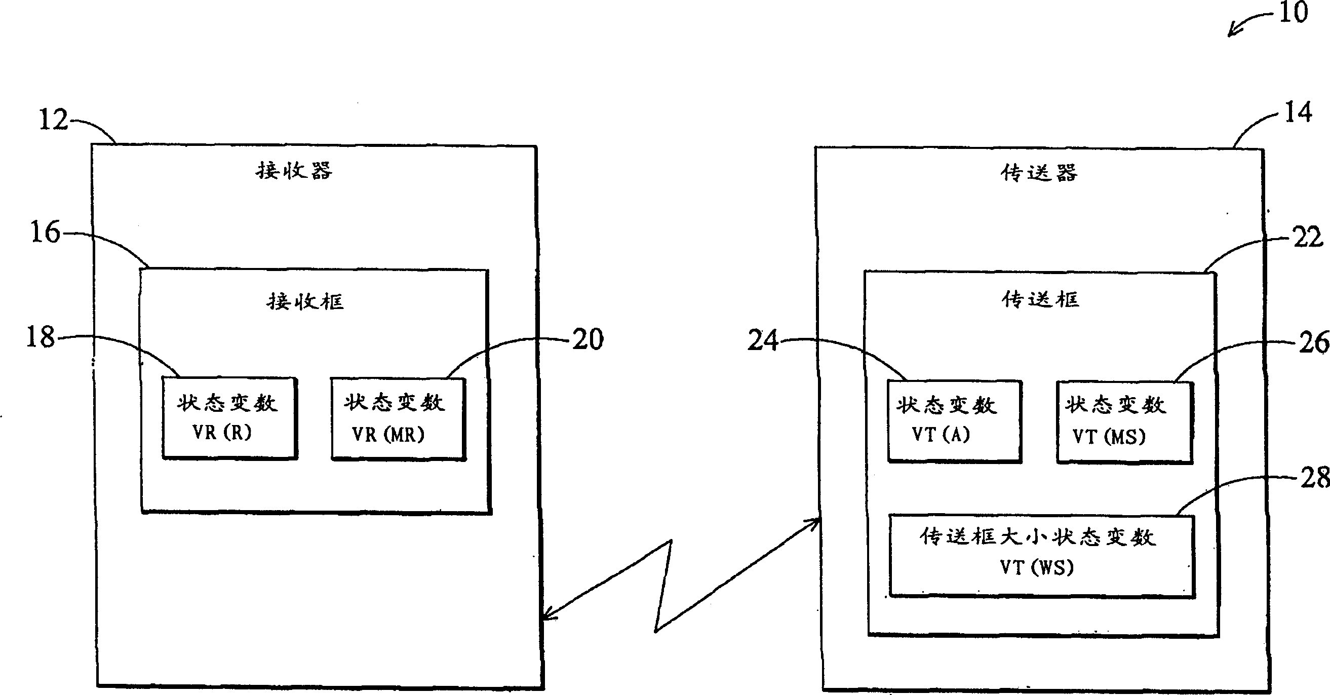
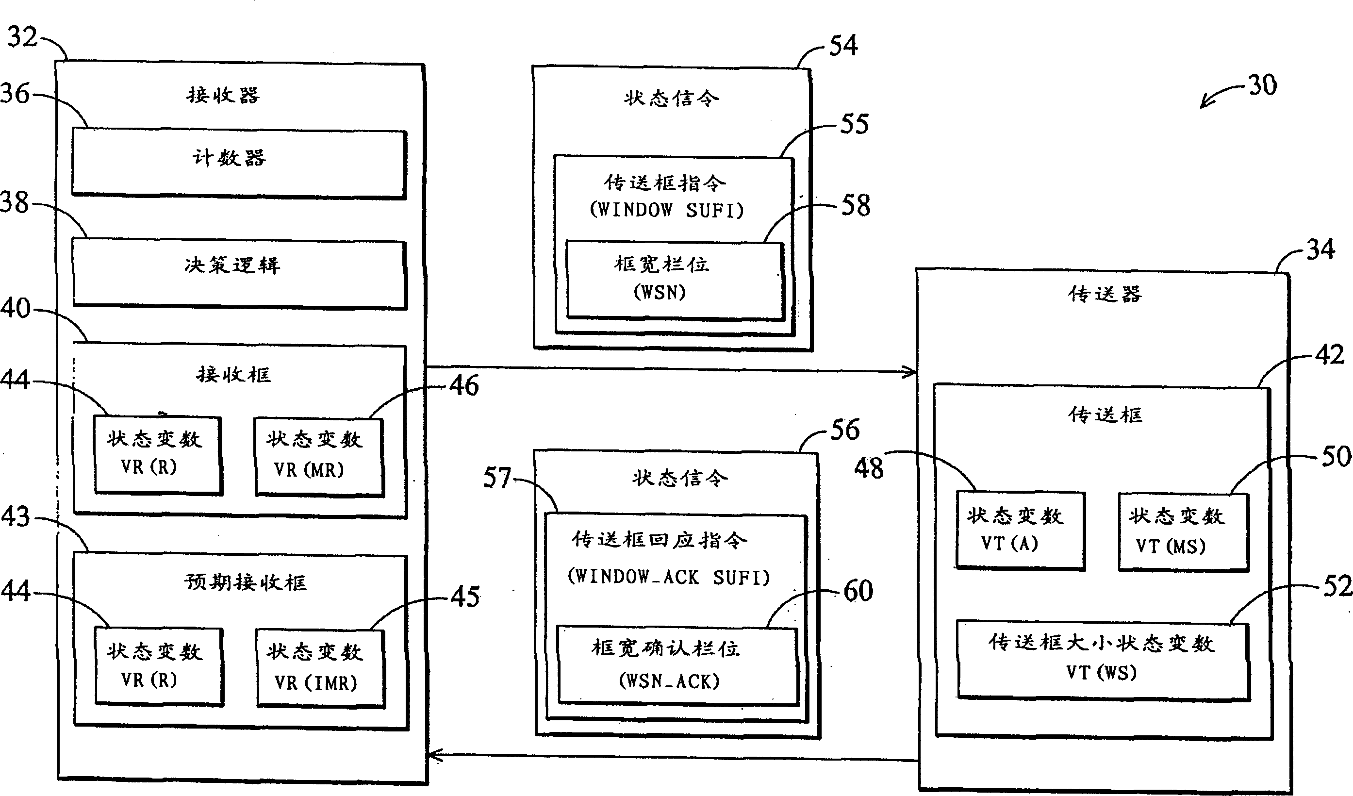
[0026] see figure 2 , figure 2A simplified block diagram of a receiver 32 and a transmitter 34 implemented in accordance with the present invention in a wireless communication system is shown. Receiver 32 has a timer 36 , decision logic 38 , and receive block 40 . The transmitter 34 establishes a sending frame 42 corresponding to the receiving frame 40 . As previously mentioned, the position or range of the receiving frame 40 is defined by two state variables VR(R) 44 and VR(MR) 46, while the position or range of the transmitting frame 42 is defined by VT(A) 48 and Defined by VT(MS)50. The transfer frame 42 has a size VT(WS)52. The receiver 32 is allowed to initiate a transmission frame adjustment procedure. Such as figure 2 As shown, the receiver 32 outputs a status signaling 54 to the transmitter 34 that includes a transmit frame command 55 , including a frame width (WSN) field 58 for changing the size of the transmit frame 42 . That is, the transfer frame instruct...


PUM


Abstract

A method of controlling a receiver and a transmitter to handle a transmission window size change procedure is disclosed. The method includes driving the receiver to deliver a control message having a window size parameter to the transmitter for adjusting a transmission window size of the transmitter, and driving the transmitter to output an acknowledgement message to the receiver and adjust the transmission window size according to the window size parameter when the transmitter receives the control message.

Description

technical field [0001] The present invention relates to a method for setting a wireless communication system, in particular to a method for processing a transmission window adjustment procedure applicable in a wireless communication system. Background technique [0002] see figure 1 , figure 1 It is a simplified block diagram of a wireless communication system 10 including a receiver 12 and a transmitter 14 in the prior art. The receiver 12 and the transmitter 14 respectively determine the size of the transmission frame according to the number of data units expected to be received or transmitted. The receiving frame 16 range of the receiver 12 is defined by two state variables, VR(R) 18 and VR(MR) 20 . Among them, VR(R)18 indicates the start sequence number of the receiving frame 16 , and VR(MR)20 indicates the end sequence number of the receiving frame 16 . The receiver 14 will only accept data units whose sequence number is equal to VR(R)18 or later, and whose sequence...

Claims


Application Information

Patent Timeline
Patent Type & Authority Applications(China)
IPC IPC(8): H04L29/06H04L1/00H04L1/18H04L12/26H04L12/56H04L29/08
CPCH04L47/18H04L47/14H04L47/263H04L47/10H04W28/18H04L1/187H04L1/188H04L47/27H04W28/04H04L1/1832H04W28/10H04L1/18H04W8/04
Inventor 江孝祥
Owner INNOVATIVE SONIC
Why Eureka
Try Eureka