Hydraulic transformer of broad voltage regulation range

A technology for hydraulic transformers and voltage regulation ranges, applied in the field of hydraulic transformers, can solve problems such as failure to consider the impact of hydraulic transformer performance, reduction of transformer energy saving effects, loss of transformer functions, etc., to solve oil throttling losses and expand voltage regulation ratios range effect

Inactive Publication Date: 2005-03-02
ZHEJIANG UNIV +1
View PDF3 Cites 9 Cited by
  • Summary
  • Abstract
  • Description
  • Claims
  • Application Information

AI Technical Summary

Problems solved by technology

In this patent, only the relationship between the valve plate and the cylinder block is considered, but the influence of the valve plate and the rear end cover on the performance of the hydraulic transformer is not considered.
[0008] In this patent, in the hydraulic transformer, the shape of the waist-shaped groove of the valve plate is consistent with that of the interface of the rear end cover. , The oil flow area between the T interface gradually decreases, the oil throttling loss between the distribution plate and the rear end cover increases, and the energy-saving effect of the transformer decreases; when the rotation angle of the distribution plate increases to a certain value, there will be Make the A slot of the distribution plate communicate with the T port of the rear end cover, the B slot and the A port, and the T slot and the B port, resulting in the loss of the function of the transformer
Therefore, the hydraulic transformer designed according to this patent has the problem of small transformer voltage regulation ratio and h

Method used


Image

  • Hydraulic transformer of broad voltage regulation range
  • Hydraulic transformer of broad voltage regulation range
  • Hydraulic transformer of broad voltage regulation range

Examples


Embodiment Construction

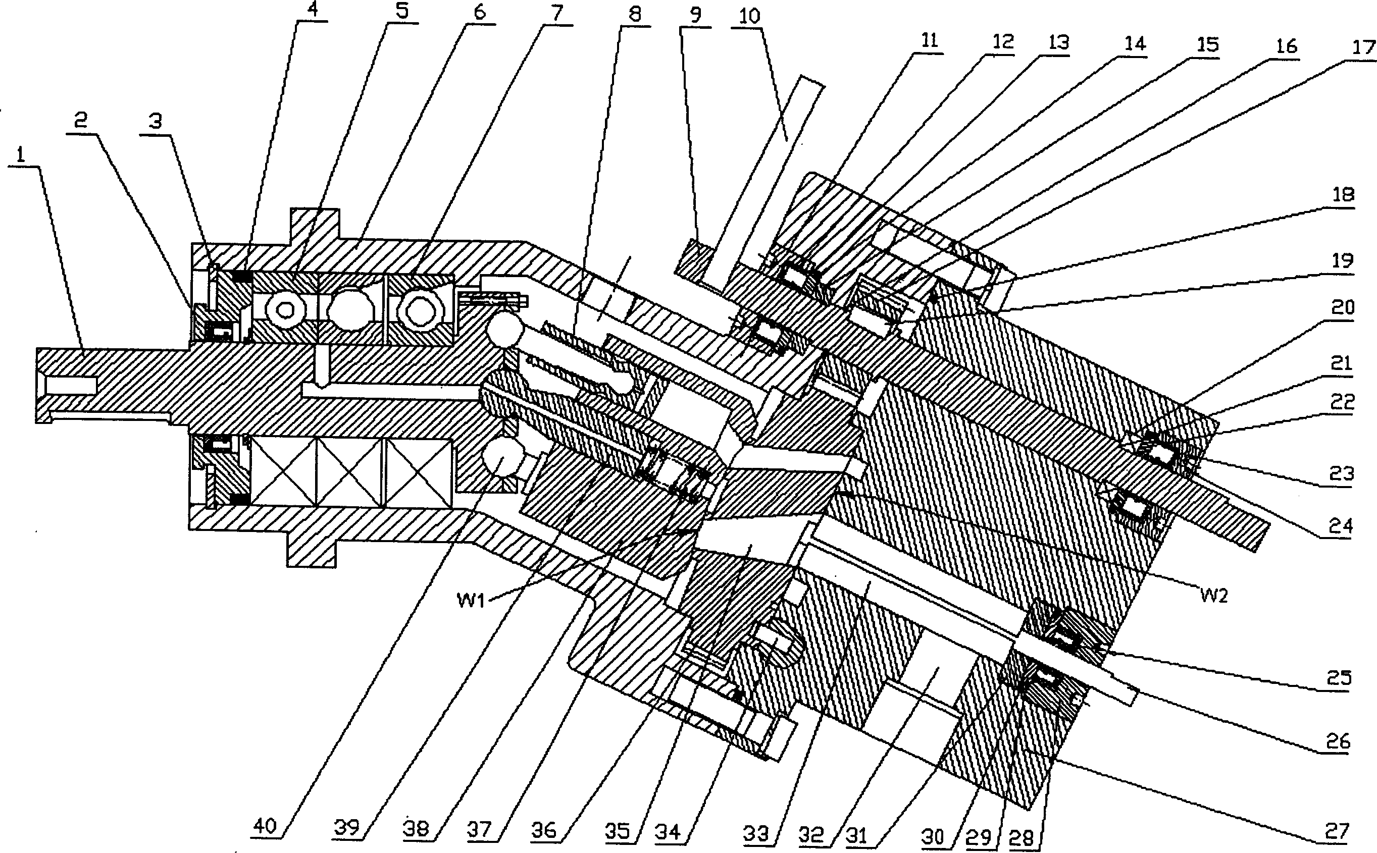
[0032] The present invention will be further described below in conjunction with drawings and embodiments.

[0033] Such as figure 1As shown, one end of the housing 6 is connected to the rear end cover 27, and the seal is formed by an O-ring 18; , so as to form a closed cavity of the oblique shaft type hydraulic transformer; one end of the main shaft 1 is installed on the rolling bearing 5 and the angular contact ball bearing 7 in the front end cover 2 hole and the housing 6, and the central shaft 39 is installed in the cylinder body 38, and the central shaft The axis of 39 intersects the axis of the main shaft 1 to form an inclined shaft structure. One end of the central shaft 39 is hinged on the main shaft 1, and the other end is installed in the central hole of the cylinder body 38, and its initial position is adjusted by the pretension spring 37 , an odd number of plungers 8, generally 5, 7, and 9 plungers, are respectively connected with the connecting rod 40 through a b...


PUM


Abstract

The invention publicizes a kind of hydraulic transformer for extending voltage-regulating range. The main shaft and center shaft intersects into obliquid shaft structure. One end of the center shaft is connected with the main-shaft, the other end is fixed in the center hole of vessel. The shaft plug and the connecting rod are connected by ball-hinge, the other end of the connectnig rid connected with the main shaft by ball hinge, and the other end of shaft-plug is laid in the shaft-plug cavity of vessel, distributing flow disc is fixed between the vessel and the back-end lid by controlling the rotating angle of the distributing flow disc and controlling the flow quantity of three oil exits of the distributing flow disc, it controls the pressure proportion of input and output. Using the special distributnig flow disc, and back-end lid structure, it resolves the damage of oil liquid throttle, enlarges the proportion range of the pressure transforming, to a greast extent, it embodies the pressure-transforming function, recycling load function, energy-saving function. In order to measure the rotating angle of the distributing flow disc, there is a angle transmission shaft.

Description

technical field [0001] The invention relates to hydraulic components, in particular to a hydraulic transformer with widened voltage regulation range. Background technique [0002] The constant pressure network secondary regulation technology developed in recent years has improved the flexibility and efficiency of the hydraulic system. However, although there are many advantages in the principle of secondary regulation, its application in the hydraulic field has been limited to a certain extent. In terms of driving the rotating load, the driving of the rotating load can be realized by adjusting the adjusting mechanism of the variable hydraulic motor. There is no good solution for driving linear loads with different load pressure requirements. Hydraulic transformers are developed under this technical background. [0003] In the patent WO 97 / 31185, a new hydraulic transformer design concept is proposed. Compared with the traditional hydraulic transformer, this type of transf...

Claims


Application Information

Patent Timeline
IPC IPC(8): F04B1/20F04B1/30F15B3/00
Inventor 徐兵翁振涛欧阳小平杨华勇马吉恩
Owner ZHEJIANG UNIV
Why Eureka
Try Eureka