
Luminous diode light source

A light-emitting diode and light source technology, applied in the field of light-emitting diode light sources, can solve problems such as increased energy consumption and reduced LED life, and achieve the effects of increasing power consumption and improving instantaneous brightness

Inactive Publication Date: 2005-03-02
WUHAN UNIV OF TECH
View PDF0 Cites 3 Cited by
  • Summary
  • Abstract
  • Description
  • Claims
  • Application Information

AI Technical Summary

Problems solved by technology

The existing LED light source can only increase the brightness of the LED light source by increasing the input voltage of the LED, which will increase the energy consumption and reduce the life of the LED.

Method used


Image

  • Luminous diode light source
  • Luminous diode light source
  • Luminous diode light source

Examples


Embodiment Construction

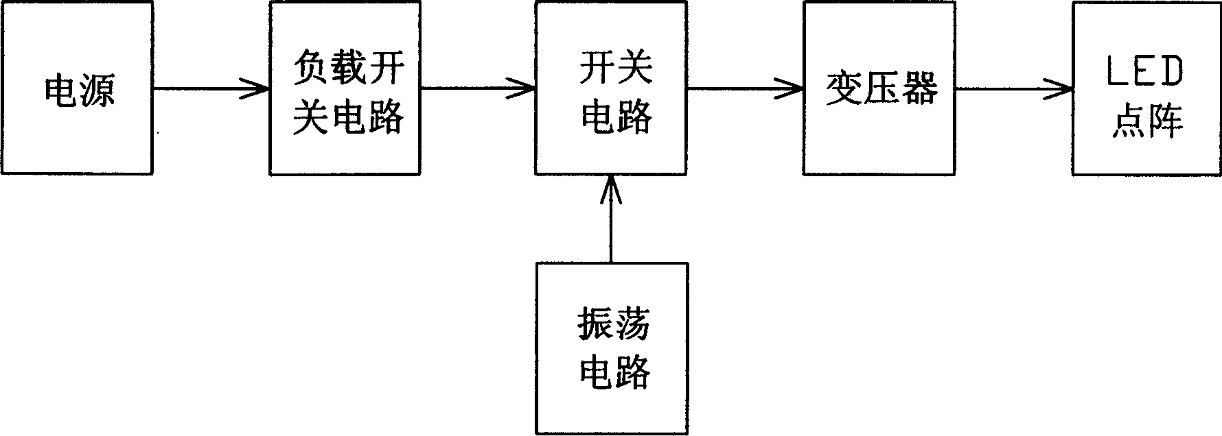
[0029] Such as figure 1 Shown embodiment 1 of LED light source of the present invention, it is the illumination of automobile and indicates LED light source, and it comprises power supply, transformer, light-emitting diode lattice, power supply provides power supply for light-emitting diode lattice through transformer; Power supply and light-emitting diode lattice There is a switch circuit between them, and the switch circuit is controlled by an oscillation circuit. The output frequency of the oscillation circuit is: 90-120Hz. A load switch circuit is provided between the power supply and the rear stage circuit.

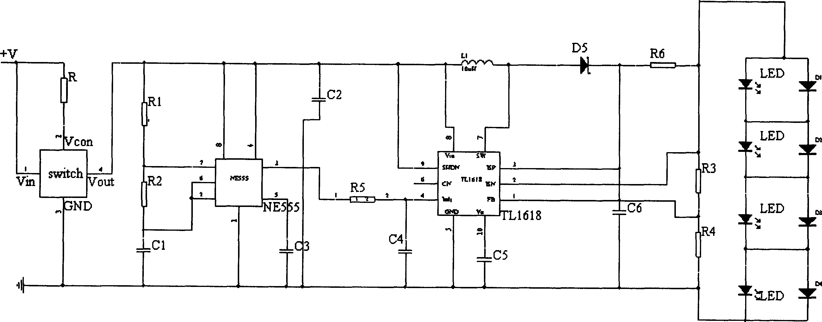
[0030] Such as image 3 The circuit diagram of Embodiment 1 of the LED light source of the present invention is shown, wherein:

[0031] The load switch circuit is a load switch circuit (switch) designed by power MOSFET. Its working principle is: only when Vin and Vcon are positive at the same time, the load switch is turned on to make the oscillation circuit and...


PUM


Abstract

This invention relates to a LED light source including a power supply, a transformer, a LED lattice, the power supply provides power to the lattice by the transformer having a switch circuit between them controlled by an oscillation circuit. The oscillation circuit and the switch circuit are set in this inverted light source circuit, the oscillation circuit generates square wave signals in a certain frequency to control the on-off of the switch circuit to control the current input into the LED and make LED lattice flash in high frequency to increase its transient brightness.

Description

technical field [0001] The present invention relates to light sources for illumination and indication, in particular light emitting diode (LED) light sources. Background technique [0002] In today's society, energy issues have become prominent issues. Lighting is an important aspect of human energy consumption. According to media reports, the use of semiconductor light source LEDs to replace traditional incandescent lighting will save 50% of global lighting energy consumption. It can be seen that in the field of electronic technology in the future, LED light sources as indicators and lighting will become another major electronic theme. [0003] LED is a solid light source. Since the appearance of GaAlInP and GaAlInN light-emitting diodes in the 1990s, the luminous efficiency and luminous intensity of LEDs have undergone breakthrough development, and high-brightness white and blue LEDs have appeared. In the 21st century, with the development of material technology, packagi...

Claims


Application Information

Patent Timeline
Patent Type & Authority Applications(China)
IPC IPC(8): H05B37/00H05B37/02
Inventor 陈汉汛吉孔武徐达伟倪尔东刘利
Owner WUHAN UNIV OF TECH
Learn More