User equipment having a hybrid parallel/serial bus interface

A serial bus interface and user equipment technology, applied in parallel/serial conversion, instrumentation, electrical digital data processing, etc., can solve problems such as increasing bus cost

Inactive Publication Date: 2005-03-02
INTERDIGITAL TECH CORP
View PDF0 Cites 0 Cited by
  • Summary
  • Abstract
  • Description
  • Claims
  • Application Information

AI Technical Summary

Problems solved by technology

Large number of pins or connections may in

Method used


Image

  • User equipment having a hybrid parallel/serial bus interface
  • User equipment having a hybrid parallel/serial bus interface
  • User equipment having a hybrid parallel/serial bus interface

Examples


Embodiment Construction

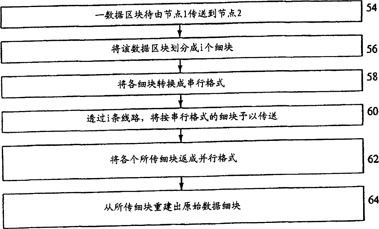
[0026] Figure 2 is a block diagram of a hybrid parallel / serial bus interface, and Figure 3 is a flow chart of a hybrid parallel / serial bus interface data transfer operation. A data block will be transferred across the interface from node 150 to node 252 (54). A data block demultiplexing device 40 receives the block, and demultiplexes it into i fine blocks to facilitate transmission on i data transmission lines 44 (56). The value i is based on the trade-off between the number of connections and the transmission speed. One way to determine the value of i is to first determine the maximum allowable delay for transmitting the data block. According to this maximum delay, the minimum number of lines required to transmit the block can be determined. Using the minimum number of lines, the line used to transmit data will be selected to be at least the minimum amount. The line 44 can be a pin and its related connection on a circuit board or an IC connection. One way to demultiplex into fine...


PUM


Abstract

A hybrid serial/parallel bus interface for a user equipment (UE) has a data block demultiplexing device. The data block demultiplexing device has an input configured to receive a data block and demultiplexes the data block into a plurality of nibbles. For each nibble, a parallel to serial converter converts the nibble into serial data. A line transfers each nibble's serial data. A serial to parallel converter converts each nibble's serial data to recover that nibble. A data block reconstruction device combines the recovered nibbles into the data block.

Description

Technical field [0001] The present invention is about bus data transfer. In particular, the present invention is to reduce the number of lines for transmitting bus data. Background technique [0002] Figure 1 shows an example of a bus used to transmit data. FIG. 1 is an explanatory diagram of a receiving and transmitting gain controller (GC) 30, 32 and a GC controller 38 used in a wireless communication system. A communication station, such as a base station or user equipment, transmits (TX) and receives (RX) signals. In order to control the gain of these signals within the operating range of other receiving / transmitting components, the GC 30, 32 adjusts the gain on the RX and TX signals. [0003] To control the gain parameters of the GC 30, 32, a GC controller 38 is used. That is, as shown in FIG. 1, the GC controller 38 uses a power control bus, such as 16 line buses 34, 36 to send the gain values ​​of the TX 36 and RX 34 signals, for example, each of them has eight lines. Alth...

Claims


Application Information

Patent Timeline
IPC IPC(8): G06F13/38H03M9/00H04L25/14H04L29/00
CPCH04L25/14H03M9/00
Inventor 约瑟·葛瑞丹艾佛瑞·史达福利堤摩西·A·亚瑟尼司
Owner INTERDIGITAL TECH CORP
Why Eureka
Try Eureka