Display having positive control mode and negative control mode permitting address according to matrix form

A technology of display and display area, applied in the direction of static indicators, instruments, identification devices, etc., to achieve the effect of reducing the shadow of segmented and non-segmented areas

Inactive Publication Date: 2005-03-09
EASTMAN KODAK CO
View PDF5 Cites 5 Cited by
  • Summary
  • Abstract
  • Description
  • Claims
  • Application Information

AI Technical Summary

Problems solved by technology

However, the device can only represent one type of image,

Method used


Image

  • Display having positive control mode and negative control mode permitting address according to matrix form
  • Display having positive control mode and negative control mode permitting address according to matrix form
  • Display having positive control mode and negative control mode permitting address according to matrix form

Examples


Embodiment Construction

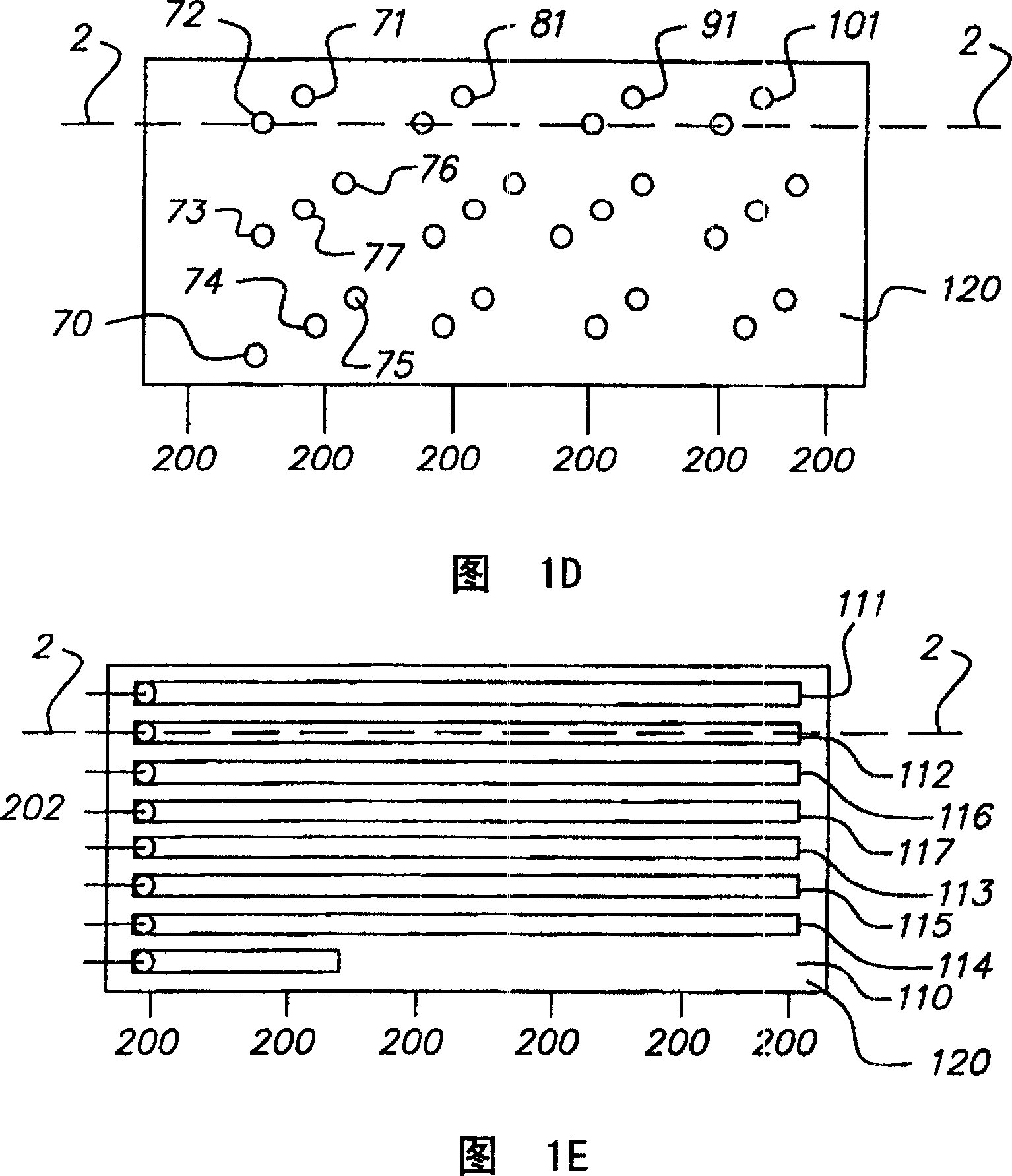
[0026] Referring to Figure 1A to Figure 2E A first method of forming a display according to the present invention is described. FIG. 1A is a top view of the first patterned conductor layer 10 of the display of the present invention. Such as Figure 2A As shown in , the display includes a substrate 15, which may be a thin transparent polymeric material such as Kodak Estar® formed of polyester plastic with a thickness between 20 and 200 microns. TM thin film substrates.

[0027] In one embodiment, substrate 15 may be a 125 micron thick polyester film substrate. Other polymers such as clear polycarbonate can also be used. Electrodes in the form of first patterned conductors 10 are formed on the substrate. The first conductor 10 can be tin oxide or indium tin oxide (ITO), wherein ITO is a preferred material. Typically, a layer of the first conductive material having a resistance of less than 250 ohms per square is sputtered on the substrate. Alternatively, the first patter...


PUM


Abstract

A method of making display having a display area capable of displaying a plurality of characters in a background, the characters including a plurality of segments, includes the steps of: providing a substrate; forming a first patterned conductor layer on the substrate having electrically separate areas defining character regions, the first patterned conductor being substantially coextensive with the display area; depositing a layer of light modulating material over the first patterned conductor layer; forming a second patterned conductor layer over the layer of light modulating material and having electrically separate areas defining the segments of the characters and the background, the second patterned conductor being substantially coextensive with the display area; depositing a dielectric layer over the second patterned conductor layer, the dielectric layer defining holes over each segment and the background area of the second patterned conductor layer; and forming a third patterned conductor layer located over the dielectric layer defining a plurality of conductors connected to the areas defining the character segments in the second patterned conductor and the background area through the holes in the dielectric layer; at least one of the conductors being connected to a segment in more than one character, whereby the display may be addressed in a matrix fashion by electrically addressing the first and second plurality of contacts, and may be driven in a positive or negative mode.

Description

technical field [0001] The present invention relates to a display with two modes of operation, addressable by a passive matrix, in particular, to a cholesteric (chiral nematic) liquid crystal display and its electrical drive mechanism, and to a segment with at least two modes of operation monitor. Background technique [0002] Referring to FIG. 4C , the prior art segmented display 1 includes a segmented area that can be written as an ON state such as segment 6 , or an OFF state such as segment 3 . Since there are no electrodes on the non-segmented area 4, the non-segmented area 4 is not addressable. Regardless of whether the segmented area is ON or OFF, the non-segmented area 4 is displayed differently from the segmented area. This produces an undesired image on the display 1 . [0003] US 5,636,044, Yuan et al., published June 3, 1997, discloses a segmented display using cholesteric liquid crystals having two substrates. The first substrate is divided into a segmented r...

Claims


Application Information

Patent Timeline
IPC IPC(8): G02F1/139G02F1/1343G02F1/1345G02F1/1347G02F1/137G09F9/30
CPCG02F1/134336G02F1/13718G02F1/134327G02F1/1345G02F2201/121
Inventor X·-D·米S·W·斯蒂芬森
Owner EASTMAN KODAK CO
Why Eureka
Try Eureka