
Video display

An image display device and image technology, which are applied in image communication, optics, instruments, etc., can solve problems such as the inability to sufficiently reduce moiré fringes.

Inactive Publication Date: 2005-03-16
SANYO ELECTRIC CO LTD
View PDF0 Cites 17 Cited by
  • Summary
  • Abstract
  • Description
  • Claims
  • Application Information

AI Technical Summary

Problems solved by technology

Moreover, in Figure 7 (a), Figure 7 (b), Figure 7 In the opening 12a shown in (c), due to the Figure 7 (a)~ Figure 7 (c) The method of diffraction between (c) is changed, so the moiré fringe cannot be sufficiently reduced

Method used


Image

  • Video display
  • Video display
  • Video display

Examples


Embodiment Construction

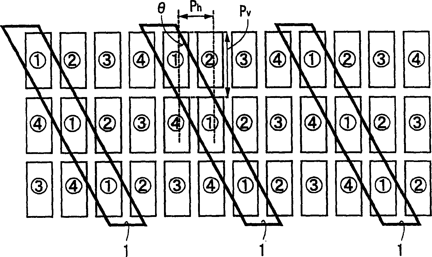
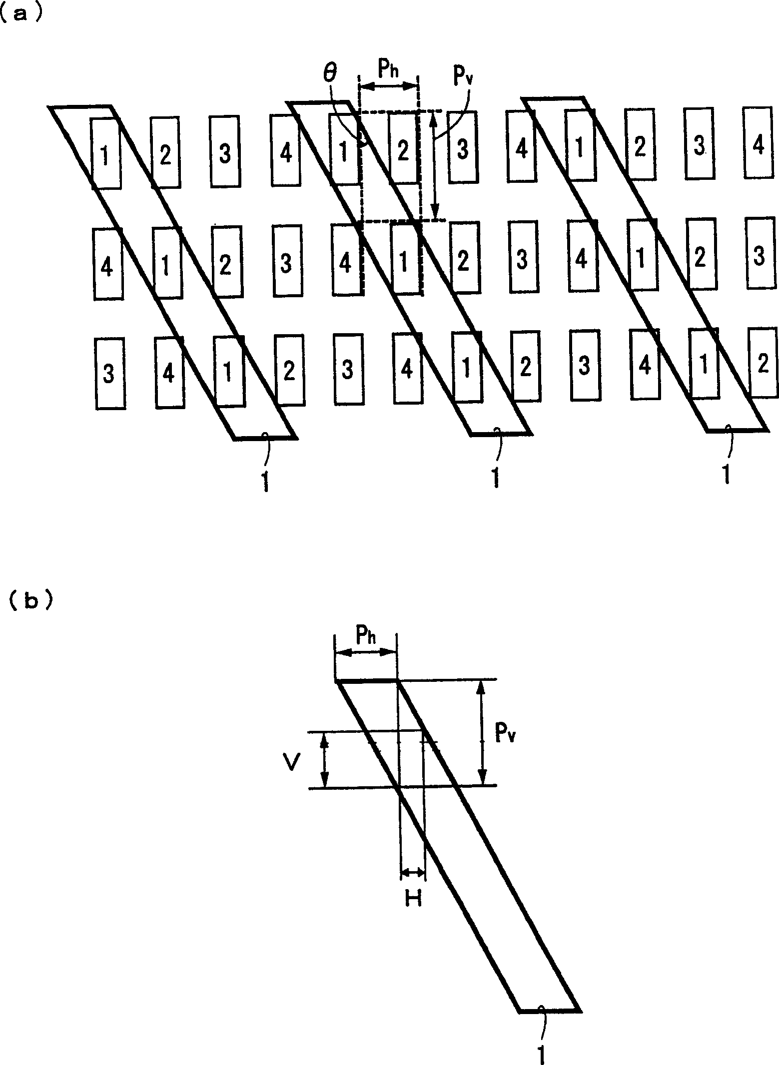
[0020] Below, according to figure 1 , figure 2 (a), figure 2 (b) An image display device according to an embodiment of the present invention will be described. Moreover, the overall configuration of the image display device can adopt the one described in the background technology item. image 3 or Figure 4 In order to avoid redundant explanations, the description of the overall configuration is omitted.

[0021] exist figure 1 In the shown four-eye configuration, four images (pixels) 'image ①, image ②, image ③, image ④' which are the minimum unit image group are repeatedly arranged in the horizontal direction of the screen. They are offset by one pixel in the horizontal direction on each row. In the case of an image display device for stereoscopic viewing, the minimum unit image group is composed of a plurality of viewpoint images, which are arranged in the above-mentioned viewpoint arrangement order (order of 1, 2, 3, 4). An edge portion defining the width of the o...


PUM


Abstract

In the case of a four-eye type stereoscopic viewing system, four videos (dots) 'video {circle over (1, video {circle over (2, video {circle over (3, and video {circle over (4', composing each of minimum units of video group are repeatedly arranged in a horizontal direction of a screen, and the minimum units of video group are arranged so as to be shifted by one dot in the horizontal direction per row. Edges for defining the width of an aperture are obliquely formed in correspondence with the shift in the horizontal direction of the minimum units of video group, and the aperture is formed so as to extend across the respective minimum units of video group on the rows, the edges being straight.

Description

technical field [0001] The present invention relates to an image display device for making observers have stereoscopic vision, or making multiple observers see different images. Background technique [0002] Conventionally, as a method of realizing stereoscopic image display without wearing special glasses, there are well-known parallax barrier method or lenticular lens method, but these methods combine images for the right eye and The image for the left eye is alternately displayed on the screen in the form of vertical stripes, for example, and the displayed image is separated by a parallax barrier or a lenticular lens and introduced into the observer's right and left eyes for stereoscopic viewing. [0003] image 3 It is an explanatory diagram illustrating the principle of a four-eye stereoscopic viewing system stereoscopic image display device. In the horizontal direction of the screen 11, images ①, image ②, image ③, and image ④ with binocular parallax are arranged at pr...

Claims


Application Information

Patent Timeline
Patent Type & Authority Applications(China)
IPC IPC(8): H04N13/04G02B27/00G02B27/22H04N9/47H04N13/00
CPCH04N13/0422H04N13/0415H04N13/0447H04N13/0409H04N13/324H04N13/31H04N13/317H04N13/351
Inventor 增谷健滨岸五郎
Owner SANYO ELECTRIC CO LTD
Learn More