Operation device

An operating device and operating surface technology, applied in mechanical control devices, instruments, sliding contact resistors, etc., can solve the problems of damaged operating touch, wrong operation, easy bending and deformation, and achieve good operability and continuous smooth operation. Effect

Inactive Publication Date: 2005-03-16
ALPS ALPINE CO LTD
View PDF2 Cites 3 Cited by
  • Summary
  • Abstract
  • Description
  • Claims
  • Application Information

AI Technical Summary

Problems solved by technology

[0009] However, in the structures shown in the above-mentioned Patent Documents 1 and 2, when a plurality of contacts are provided at very narrow intervals, in order to reliably input each contact, it is necessary to form a surface sheet with a material of a certain degree of softness, and make it easy to bend a...

Method used


Image

  • Operation device
  • Operation device
  • Operation device

Examples


Embodiment 1

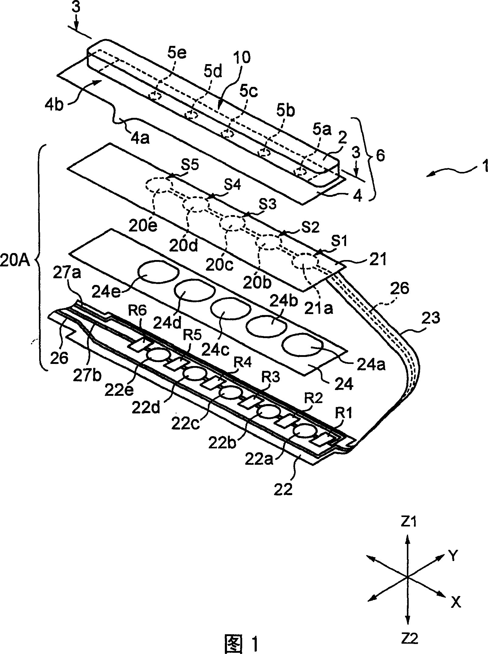
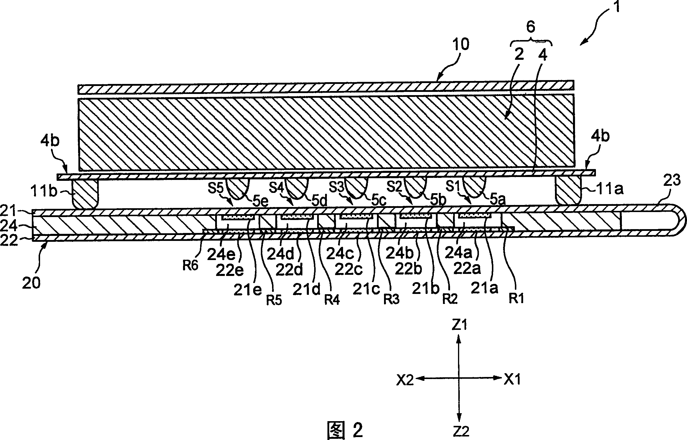
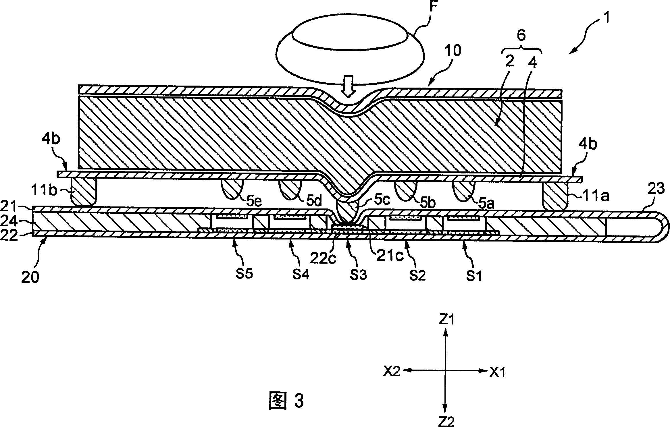
[0051] Next, as Example 1, the specific structure of the upper sheet 21 and the lower sheet 22 constituting the detection means 20A will be described.

[0052] As shown in FIG. 1, the first conductive portions 21a to 22e of the upper sheet 21 are connected in series with wires, and the lead pattern 26 is connected to 21a of the first conductive portion at the tip. The above-mentioned drawing pattern 26 is drawn to the outside of the detection mechanism 20A through the above-mentioned flexible sheet 23 and the lower side sheet 22.

[0053] Resistors R1, R2, R3, R4, R5, and R6 are printed on both ends of the second conductive portions 22a-22e provided on the lower sheet 22, respectively. The number of the resistors R1 to R6 is one more than the number of the switch parts S1 to S5. Thus, in accordance with the resistor R1, the second conductive portion 22a, the resistor R2, the second conductive portion 22b, the resistor R3, the second conductive portion 22c, the resistor R4, the sec...

Embodiment 2

[0079] Figure 5 It is a perspective view showing the detection mechanism 20B of the second embodiment of the present invention. among them, Figure 5 The spacer is omitted in the.

[0080] Figure 5 The detection mechanism 20B shown is different in that a band-shaped resistor 22B extending in the X direction in the figure is formed on the lower sheet (second sheet) 22. The strip resistor 22B described above is a resistor whose resistance value changes in proportion to the length in the X direction.

[0081] In the second embodiment, the switch parts S1, S2, S3, S4, and S5 are formed between the strip resistor 22B and the first conductive parts 21a to 21e, respectively.

[0082] Even when using Figure 5 In the operating device of the detection mechanism 20B shown, if the finger F is lightly pressed in the Z2 direction while being pressed against any one of the switch parts S1 to S5, the reinforcing member 4 is bent and deformed, and the protrusions are also pressed in the Z2 dir...

Embodiment 3

[0090] Figure 6 Is a perspective view showing the detection mechanism 20C of the third embodiment of the present invention, Figure 7 It is an equivalent circuit diagram showing the circuit configuration equivalent to the operation device adopted in the third embodiment. Table 3 shows the output current I corresponding to the operation of each switch section.

[0091] Figure 6 The illustrated embodiment 3 has substantially the same structure as the foregoing embodiment 1 shown in FIG. 1, but the difference lies in the structure that the lead pattern 27b and the resistor R6 are removed from the lower sheet 22 described above.

[0092] In Example 3, each of the first conductive portions 21a to 21e and the second conductive portions 22a to 22 constitutes the switch portions S1, S2, S3, S4, and S5, respectively. Furthermore, the lead pattern 27a of the detection mechanism 20C is connected to the power supply Vcc, and the lead pattern 26 is grounded, and the detection mechanism 20C...


PUM


Abstract

Provided is an operation device capable of being mounted on a small electronic apparatus and allowing various kinds of operations. A film-like reinforcing member 4 formed of PET or the like is fixed to the undersurface of an elastic member 2 formed of silicone rubber, and a detection means 20A is fixed to its lower part. An operation surface 10 formed of a resin layer having low friction resistance is formed on a surface of the elastic member 2. When the operation surface 10 corresponding to switch parts S1-S5 is pressed, the elastic member 2 and the reinforcing member 4 are locally deformed, and projections 5a-5e turn on the switch parts S1-S5 provided for the detection means 20A. Since the output voltage of an extraction pattern 26 is different on the basis of ON states of the switch parts S1-S5, which switch part is operated can be detected from the output voltage.

Description

Technical field [0001] The present invention relates to a push-type operating device that can be mounted on a small electronic device, and more particularly to an operating device that can reliably perform input operations even when it is downsized. Background technique [0002] As a conventional push-type operating device, there are devices disclosed in Patent Document 1 and Patent Document 2 described below. [0003] The device described in Patent Document 1 described below is composed of a switch electrode pair obtained by arranging a plurality of membrane switches facing each other on a base film that can be folded through a spacer. One switch electrode pair is connected to the same potential via a wire, and the other switch electrode pair is connected via a strip resistor. [0004] If any one of the membrane switches is operated, the operation of each membrane switch outputs a voltage value of a level corresponding to the aforementioned band resistance. For this reason, it c...

Claims


Application Information

Patent Timeline
IPC IPC(8): H01H13/712G05G1/00H01C10/38H01H13/14H01H13/70
Inventor 西岛章夫志贺贞一
Owner ALPS ALPINE CO LTD
Why Eureka
Try Eureka