Automatic monitoring apparatus for operating state of navigational aid lamp

A technology for automatic monitoring and working status, which is applied in the direction of lighting devices, measuring devices, lamp circuit layout, etc.

Inactive Publication Date: 2010-12-08
周洪璋 +1
View PDF6 Cites 0 Cited by
  • Summary
  • Abstract
  • Description
  • Claims
  • Application Information

AI Technical Summary

Problems solved by technology

[0010] The present invention is to provide an automatic monitoring device for the working state of the navigation light to solve the technical problem of realizing single-light control of the target light and two-way transmission of open circuit and fault location display

Method used


Image

  • Automatic monitoring apparatus for operating state of navigational aid lamp
  • Automatic monitoring apparatus for operating state of navigational aid lamp
  • Automatic monitoring apparatus for operating state of navigational aid lamp

Examples


Embodiment Construction

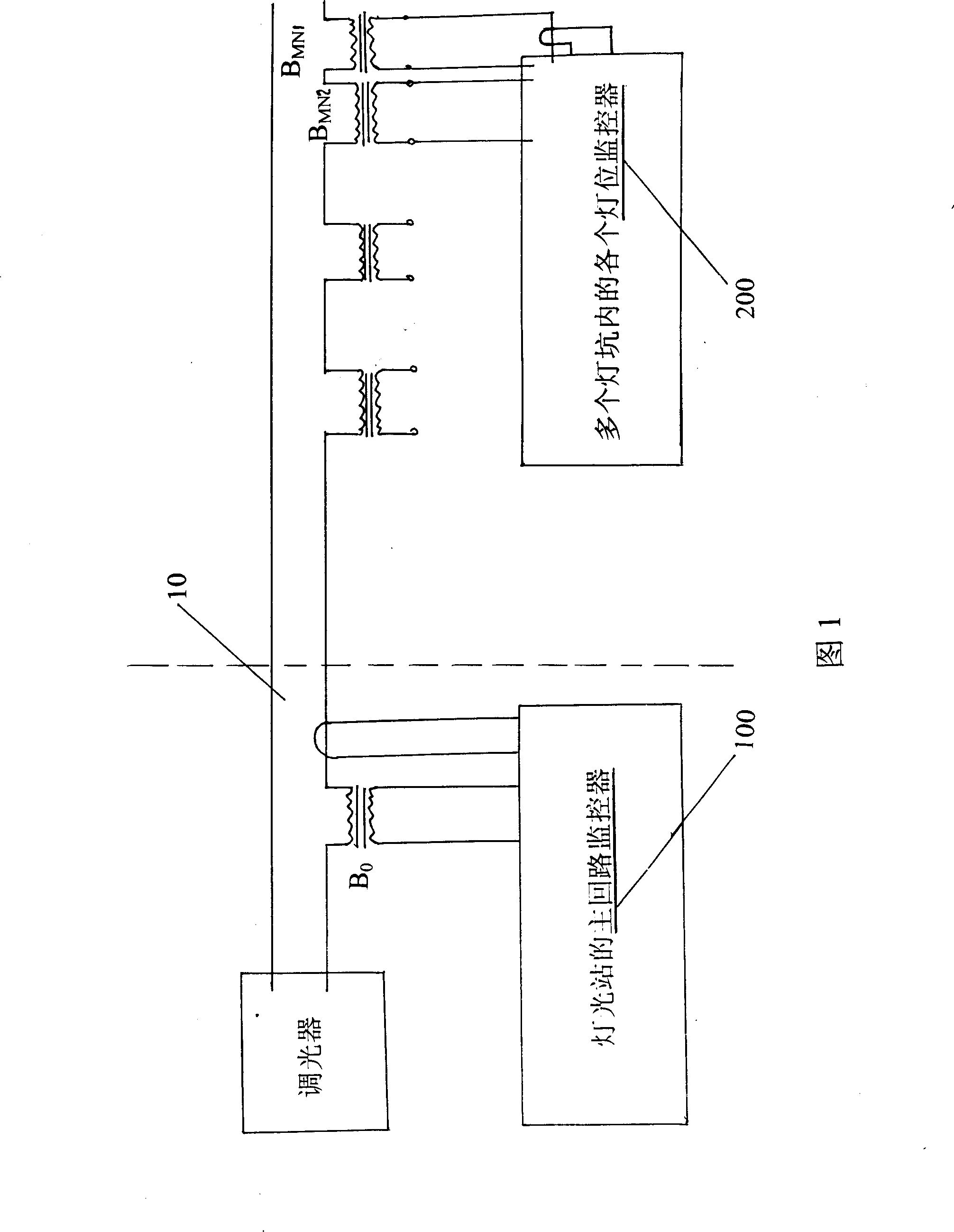
[0034] Such as figure 1 As shown, the principle block diagram of the present invention includes a dimmer main circuit 10, a main circuit monitor 100 located in a lighting station, and various lamp position monitors 200 in a plurality of lamp pits.

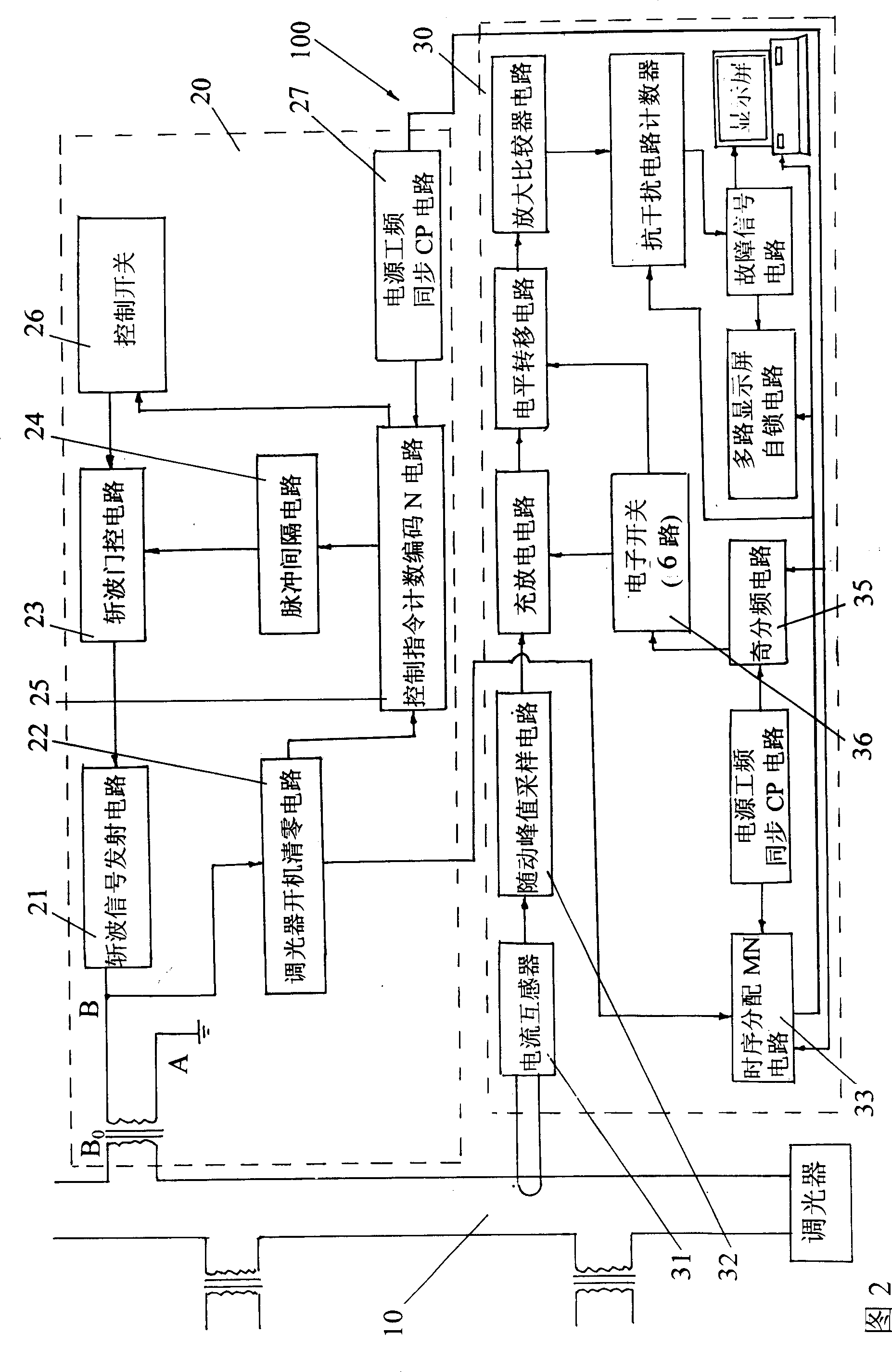
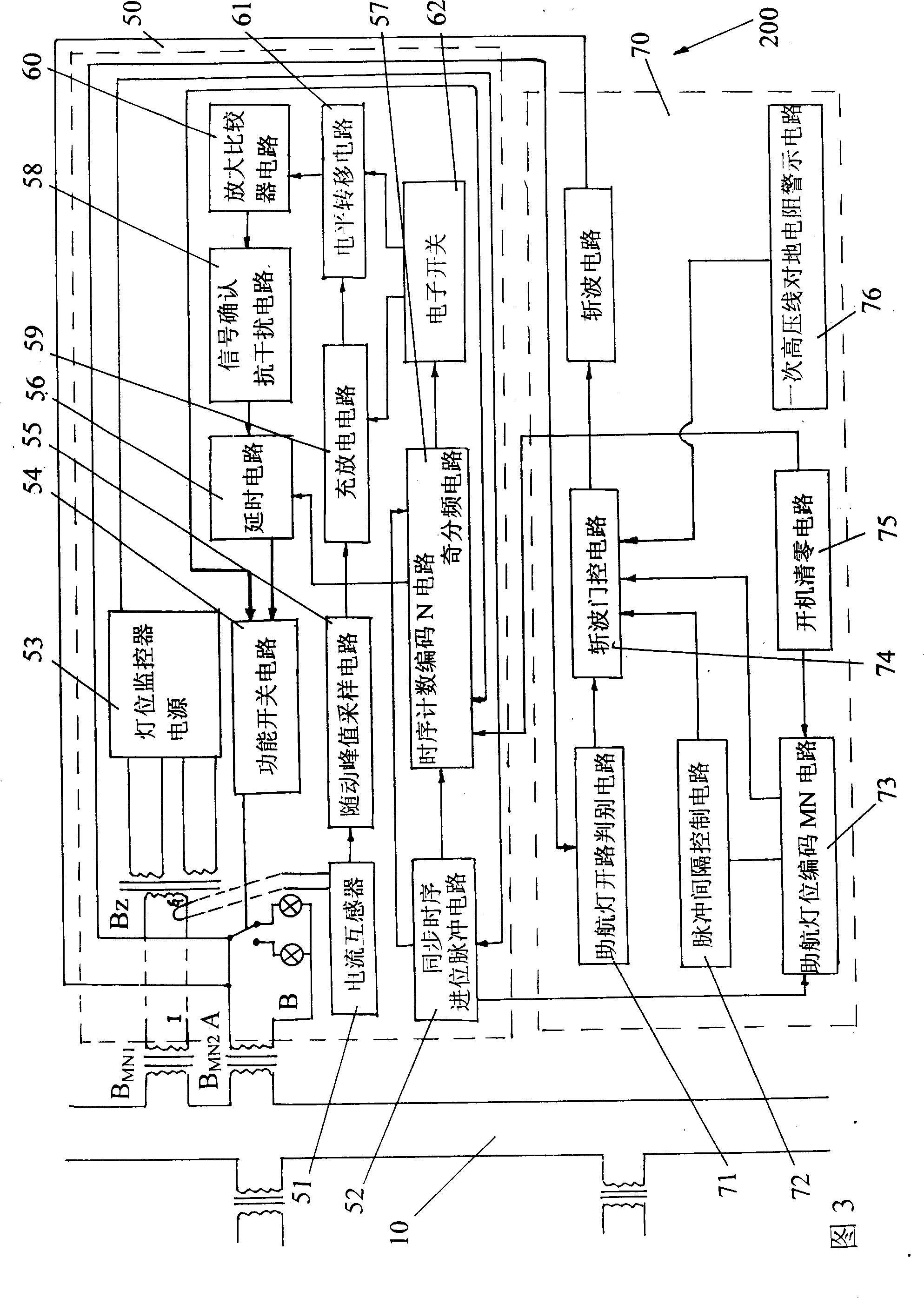
[0035] Such as figure 2 As shown in the figure, it is a block diagram of the electrical principle of the main circuit monitor of the lighting station, such as image 3 As shown, it is a schematic block diagram of the electrical principle of each lamp position monitor located in multiple lamp pits. With the help of the main circuit 10 of the primary high-voltage line of the dimmer, the two-way transmission of signals is realized by using the power supply 50HZ power frequency synchronous chopping technology and the principle of time domain distribution. .

[0036] The power supply required for the main circuit monitor to transmit and receive is shown in the figure, where figure 2 The working power supply of the main circuit moni...


PUM


Abstract

The invention is an automatic monitoring device for navaid light state. It includes dimmer powering primary loop, primary loop monitor and light position monitor in each light pit, the primary loop monitor is arranged with a receiving circuit, the light position monitor is arranged with a ejecting circuit. Its character lies in: there has a emitting circuit in the primary monitor, which includes isolating transformer B0, chopped wave signal ejecting circuit, dimmer reset circuit, chopped wave gating circuit, pulse isolating circuit, control instruction counting and coding N circuit, power industry frequency synchronous CP circuit and control switch K; the light position monitor is arranged with a receiving circuit, which including isolation transformer BMN, special transformer BZ, currentmutual inductor Hn, light position monitor power, follow-up peak sampling circuit, function switch circuit, delay circuit, it realizes the double-direction transmission and control of light position and light station with a long distance.

Description

technical field [0001] The invention relates to an automatic monitoring device, in particular to an automatic monitoring device for the working state of navigation lights which realizes single-light control and two-way transmission of positioning display. Background technique [0002] According to the relevant standards of the International Civil Aviation Organization, the navigation lights are powered by AC series, that is, the dimmer power supply outputs a constant current (the light level is determined by the current 2.8A ~ 6.6A divided into five levels), through each isolation transformer primary side It is connected in series to form a high-voltage circuit, and the secondary side of the isolation transformer outputs a low voltage for lighting the navigation lights. It can be seen that it is safe to automatically detect and control the working status of the navigation lights at the low-voltage side of the secondary side, but due to the shielding and isolation effect of t...

Claims


Application Information

Patent Timeline
Patent Type & Authority Patents(China)
IPC IPC(8): H05B37/02G01R19/00
Inventor 周洪璋刘承沛王冰松陈敏生周桐袁伟何跃
Owner 周洪璋
Why Eureka
Try Eureka