Light stuffing mould component for concrete poured-in-situs

A technology of cast-in-place concrete and components, which is applied in the direction of building components, building structures, floor slabs, etc., can solve the problems of affecting floor construction quality, affecting construction efficiency, and inconvenient positioning, and achieves simple structure, improved construction efficiency, and positioning convenient effect

Inactive Publication Date: 2005-03-23
湖南邱则有专利战略策划有限公司
View PDF2 Cites 10 Cited by
  • Summary
  • Abstract
  • Description
  • Claims
  • Application Information

AI Technical Summary

Problems solved by technology

The above-mentioned solid cast-in-place concrete light-weight tire mold members are applied to cast-in-place concrete floors, and are both formwork members and prefabricated filling members, with simple structure, high strength, excellent deformation resistance and vibration resistance. , easy to manufacture, low cost, etc. However, when this lightweight tire formwork member is constructed, it needs to be constructed individually, and it is inconvenient to locate each other, and it is prone to misalignment, which affects the construction quality of the floor and also affects the construction efficiency. Therefore, , it is urgently needed to develop a new type of lightweight tire mold member for cast-in-place concrete

Method used


Image

  • Light stuffing mould component for concrete poured-in-situs
  • Light stuffing mould component for concrete poured-in-situs
  • Light stuffing mould component for concrete poured-in-situs

Examples


Embodiment Construction

[0042] The present invention will be further described below in conjunction with the accompanying drawings and embodiments.

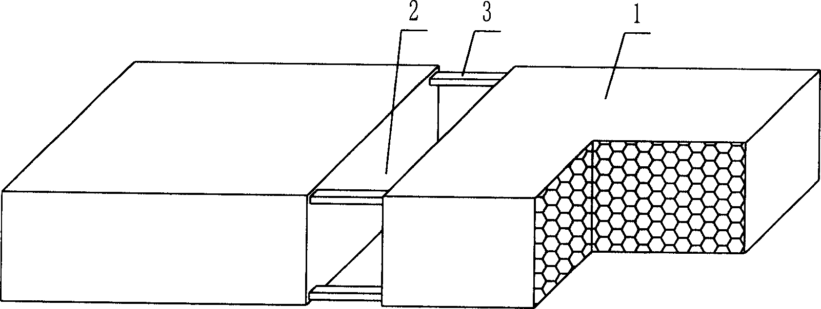
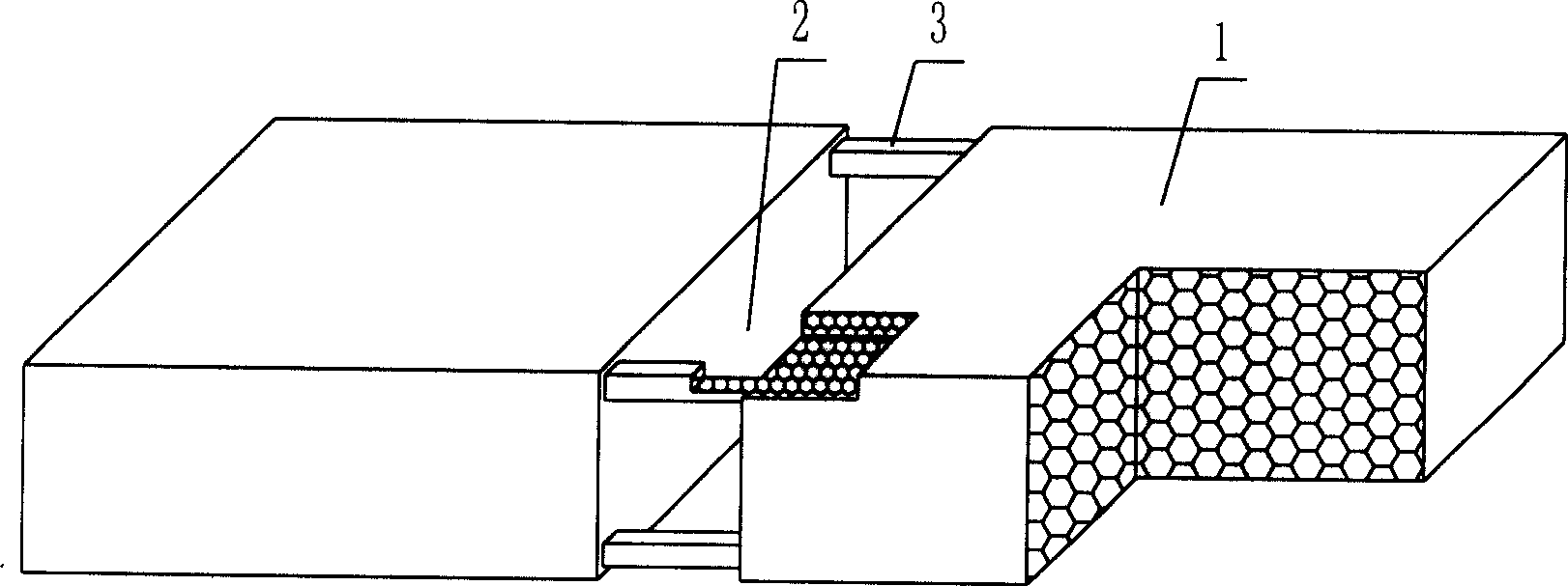
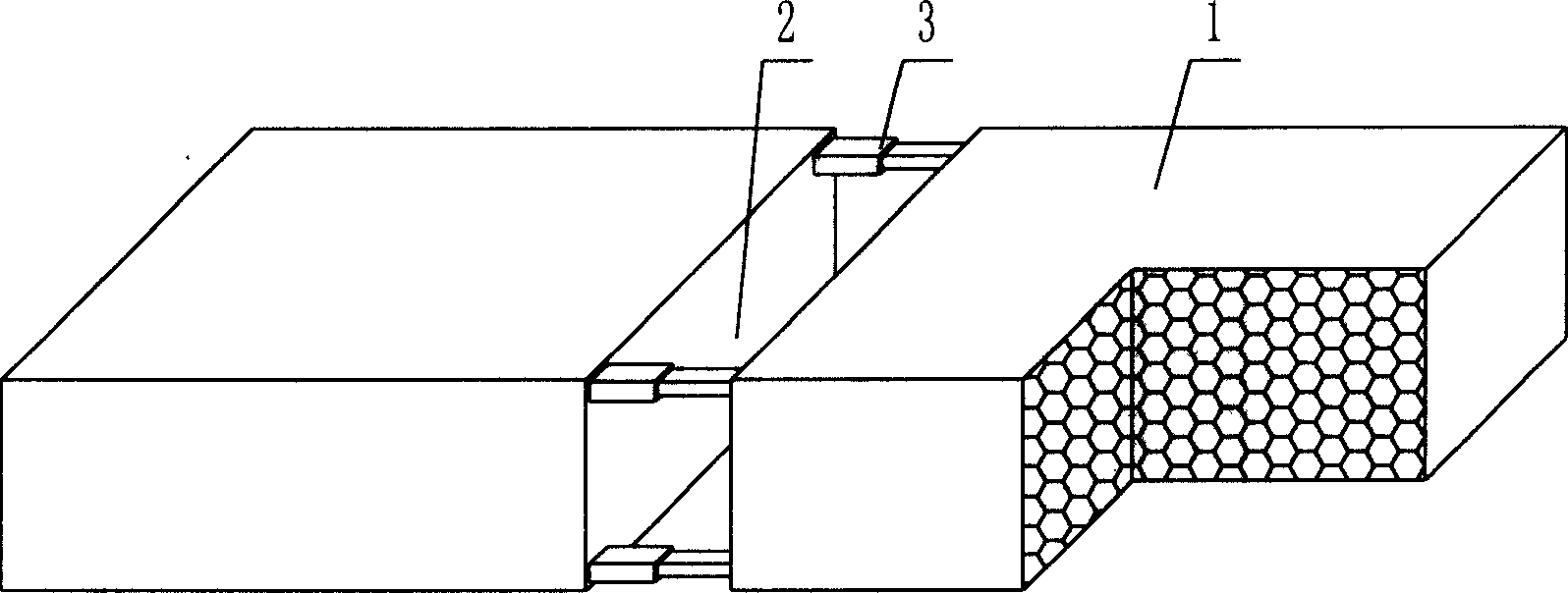
[0043] As shown in the accompanying drawings, the present invention comprises a polyhedral solid lightweight material member 1, which is characterized in that at least two polyhedral solid lightweight material members 1 are arranged alternately to form an inner rib cavity 2 between each other, and in the inner rib cavity 2 there are At least one spacer brace 3 that connects the opposite or adjacent polyhedral solid lightweight material components 1 with each other. figure 1 It is a structural schematic diagram of Embodiment 1 of the present invention. In the accompanying drawings, 1 is a polyhedral solid lightweight material member, 2 is an inner rib cavity, and 3 is a spacer brace. In the following drawings, those with the same number have the same description. Such as figure 1 As shown, two polyhedral solid lightweight material components 1 are arra...


PUM


Abstract

A light mold component that is cast-in-place concrete. It includes polyhedron solid light material component. Its feature is that at least two polyhedrons solid light material component alternated arranged with each other, and forms inner pleura cavity. At least one alternated interval support and pull component alternated combined with each other by opposite or consecutive polyhedron solid light material component in the pleura cavity. It is suited for kinds of active pouring concrete or pre-stressing force reinforcing steel bar for building casing, wall, basis bottom board and bridge, especially suited for girderless building casing.

Description

(1) Technical field [0001] The invention relates to a lightweight tire mold component for cast-in-place concrete. (2) Background technology [0002] At present, the cast-in-place concrete floor is a widely used floor structure. The lightweight permanent tire mold filled in it has various hollow tubes and boxes, and the boxes are hollow or solid. For example, the patent No. ZL00203695.9 applied by Liang Jun, Shijiazhuang City, Hebei Province on February 23, 2000, is called the utility model patent of "combined concrete concealed rib floor cover", and a formwork member is disclosed in its specification sheet. It can be solid or hollow, and its shape can be made into rectangle, circle, polygon and other shapes according to design requirements. Another example is the patent No. ZL01206422.X invented and applied by Guiyang Ma Kejian et al., and the name is the utility model patent of "built-in formwork for fasting sandwich panels". The built-in formwork is solid, and the formwor...

Claims


Application Information

Patent Timeline
Patent Type & Authority Applications(China)
IPC IPC(8): E04B5/36
Inventor 邱则有
Owner 湖南邱则有专利战略策划有限公司
Why Eureka
Try Eureka