Air-hydraulic cylinder with dual function diaphragm

A hydraulic cylinder, double-acting technology, applied in the direction of fluid pressure actuators, reciprocating piston engines, reciprocating engines with elastic walls, etc., can solve the problems of sealing elements leakage, jamming, and inability to complete cycle work, etc.

Inactive Publication Date: 2005-03-23
马成贵
View PDF0 Cites 6 Cited by
  • Summary
  • Abstract
  • Description
  • Claims
  • Application Information

AI Technical Summary

Problems solved by technology

There are serious defects in such a structure: the piston reciprocatingly slides in the cylinder to generate sliding friction or is easily stuck by foreign matter, resulting in damage to the sealing element, resulting in leakage and blocked movement, resulting in weakness and crawling. In severe cases, it will make it Stuck and unable to work; In addition, the same defect exists between the piston rod and the seal
The problem is that the spring force used in the diaphragm cylinder with such a structure cannot be too large
In this way, it is impossible to complete the cyclic work for the work occasions that require a large back and forth force.
Therefore, the scope of application of this single-acting diaphragm cylinder is greatly limited.

Method used


Image

  • Air-hydraulic cylinder with dual function diaphragm
  • Air-hydraulic cylinder with dual function diaphragm

Examples


example 1

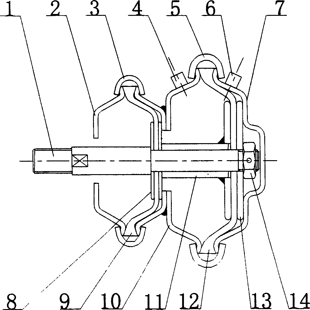
[0013] Example 1, from attached figure 1 It is shown that the present invention is a double-diaphragm, double-acting gas and hydraulic cylinder without a return spring. The overall air and hydraulic cylinder housing is composed of the front housing 2, the middle housing 10 and the rear housing 7: wherein, the front shell and the rear shell of the middle housing 10 are connected together by welding, and then the front shell 2. A small die 9 is sandwiched between the middle shell 10 and assembled together by a small clamp 3; a large die 12 is sandwiched between the middle shell 10 and the rear shell 7 and assembled together by a large clamp 5 . In order to enhance the strength of the diaphragm, when assembling the push rod, the large and small diaphragms should be assembled with two pressing plates, namely the large pressing plate 13 and the small pressing plate 8 . Push rod 1 passes large diaphragm 12, small diaphragm 9 and the pressing plate that is pressed on the front and ...

example 2

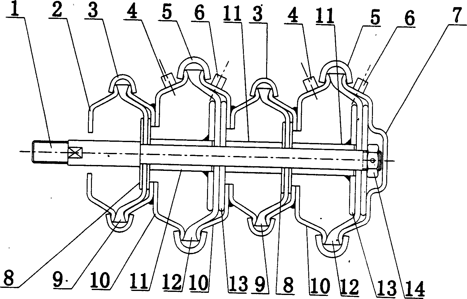
[0014] Example 2: From attached figure 2 As shown, it is composed of two sets of double-acting diaphragm air and hydraulic cylinders. The assembly of the main components is the same as in Example 1. The front casing of the cylinder is assembled together by welding, the push rod 1 passes through 4 diaphragms, its end is on the last large diaphragm, and is fixed by a nut 14, thus figure 1 The rodless cavity of the front group of air and hydraulic cylinders in the middle is changed into a rod cavity, the rear shell 7 is changed into an intermediate shell 10, the rodless gas and liquid nozzle 6 is renamed gas and liquid nozzle b, and the rod cavity gas and liquid nozzle 4 Rename the gas and liquid nozzle a.

[0015] In application, the two gas and liquid nozzles b take in air or liquid at the same time, and the two air and liquid nozzles a simultaneously exhaust or liquid. Under the same pressure, the force generated by the large diaphragm 12 of the previous group is greater tha...


PUM


Abstract

The invention relates to a double-effect film air pressure or hydraulic cylinder using pressure air or liquid as power, which includes the shell and film of the cylinder. The double-effect film plate air pressure or hydraulic cylinder is made up of at least one group, each shell is assembled with two film plates including a big one and small one, and forms tow sealed cavities, which is divided into cavity with pole and cavity without pole; the pushing pole penetrates the two film plate, and they are connected to the film plate and sealed. There has a cavity air and liquid nozzle in the cavity with a pole on top of the middle shell and the post shell, and the inlet and outlet of the air pressure and hydraulic in the cavity without pole; according to the demands, it can form several groups of double-effect film plate air pressure and hydraulic cylinder, thus the air pressure and hydraulic pushing poles can generate multiplied forces.

Description

technical field [0001] The invention relates to an actuator powered by pressurized gas or liquid, in particular to a double-acting diaphragm gas and hydraulic cylinder powered by pressurized gas or liquid. Background technique [0002] At present, most of the gas and hydraulic cylinders of the known technology are piston-type structures. There are serious defects in such a structure: the piston reciprocatingly slides in the cylinder to generate sliding friction or is easily stuck by foreign matter, resulting in damage to the sealing element, resulting in leakage and blocked movement, resulting in weakness and crawling. In severe cases, it will make it Stuck and unable to work; In addition, the same defect also exists between the piston rod and the seal. With the development of technology, a single-acting diaphragm cylinder has appeared at present. Although it overcomes the above-mentioned defects of the piston type structure, such a diaphragm cylinder can only push the push...

Claims


Application Information

Patent Timeline
Patent Type & Authority Applications(China)
IPC IPC(8): F01B19/02F03C99/00F03G7/00F15B15/10F15B15/20
Inventor 马成贵程坦
Owner 马成贵
Why Eureka
Try Eureka