Reversing gear looking mechanism of engine for motorcycle

A technology of engine and reverse gear lock, applied in mechanical equipment, vehicle parts, transmission control and other directions, can solve the problems of unsafe hidden danger, unclear memory, driver's misoperation, etc., to achieve the effect of convenient operation and simple structure

Inactive Publication Date: 2005-03-23
力帆科技(集团)股份有限公司
View PDF0 Cites 6 Cited by
  • Summary
  • Abstract
  • Description
  • Claims
  • Application Information

AI Technical Summary

Problems solved by technology

Although this operation is very convenient, it is easy to cause the driver to misuse, and often step on it twice, and he can't remember how many times he has stepped on, and he doesn't know what gear he is in.
Since the reverse gear sequence of the motorcycle engine is: reverse gear→neutral gear→1st gear→2nd gear→3rd gear→4th gear, then 4th gear→3rd gear→2nd

Method used


Image

  • Reversing gear looking mechanism of engine for motorcycle
  • Reversing gear looking mechanism of engine for motorcycle
  • Reversing gear looking mechanism of engine for motorcycle

Examples


Embodiment Construction

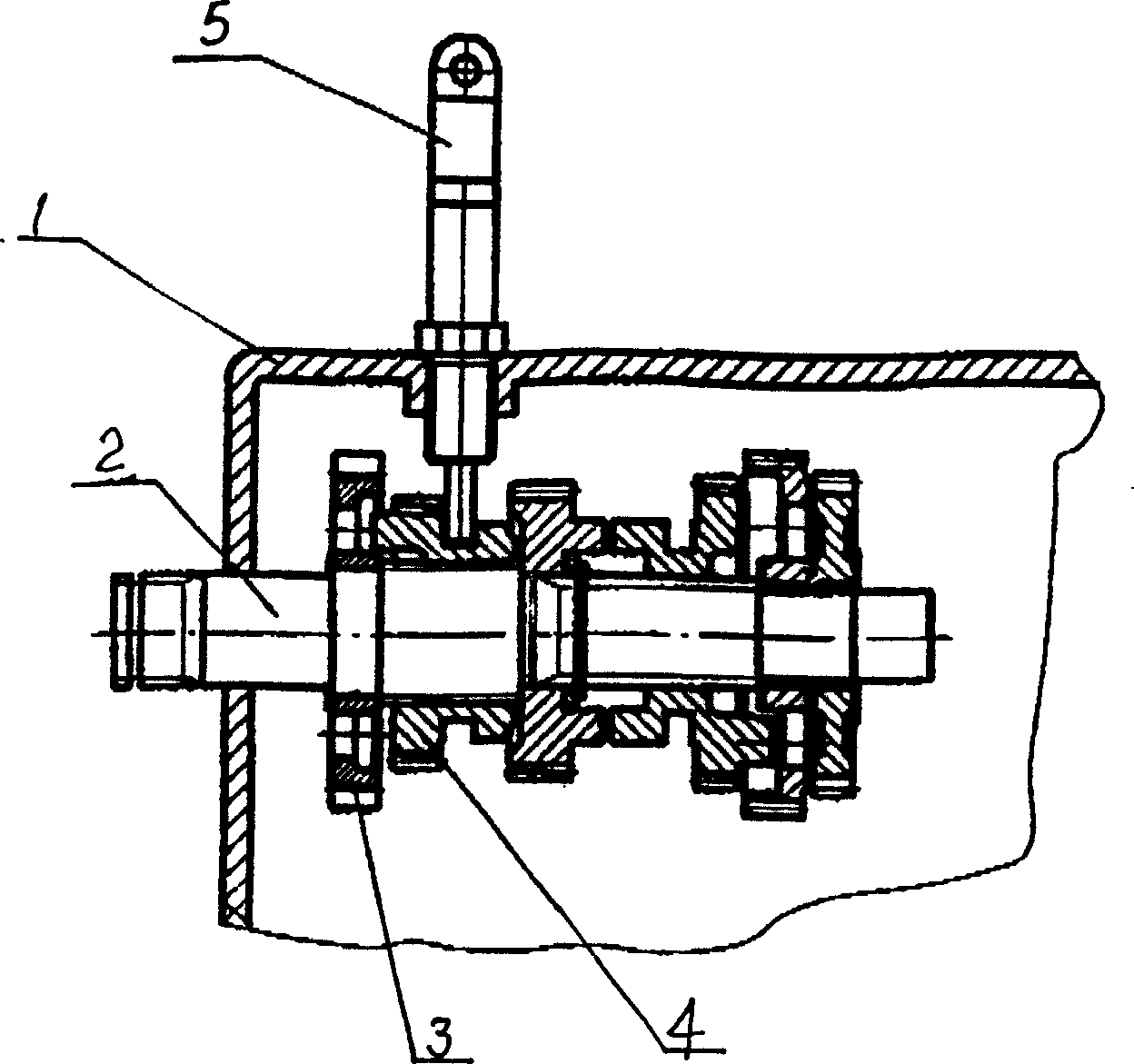
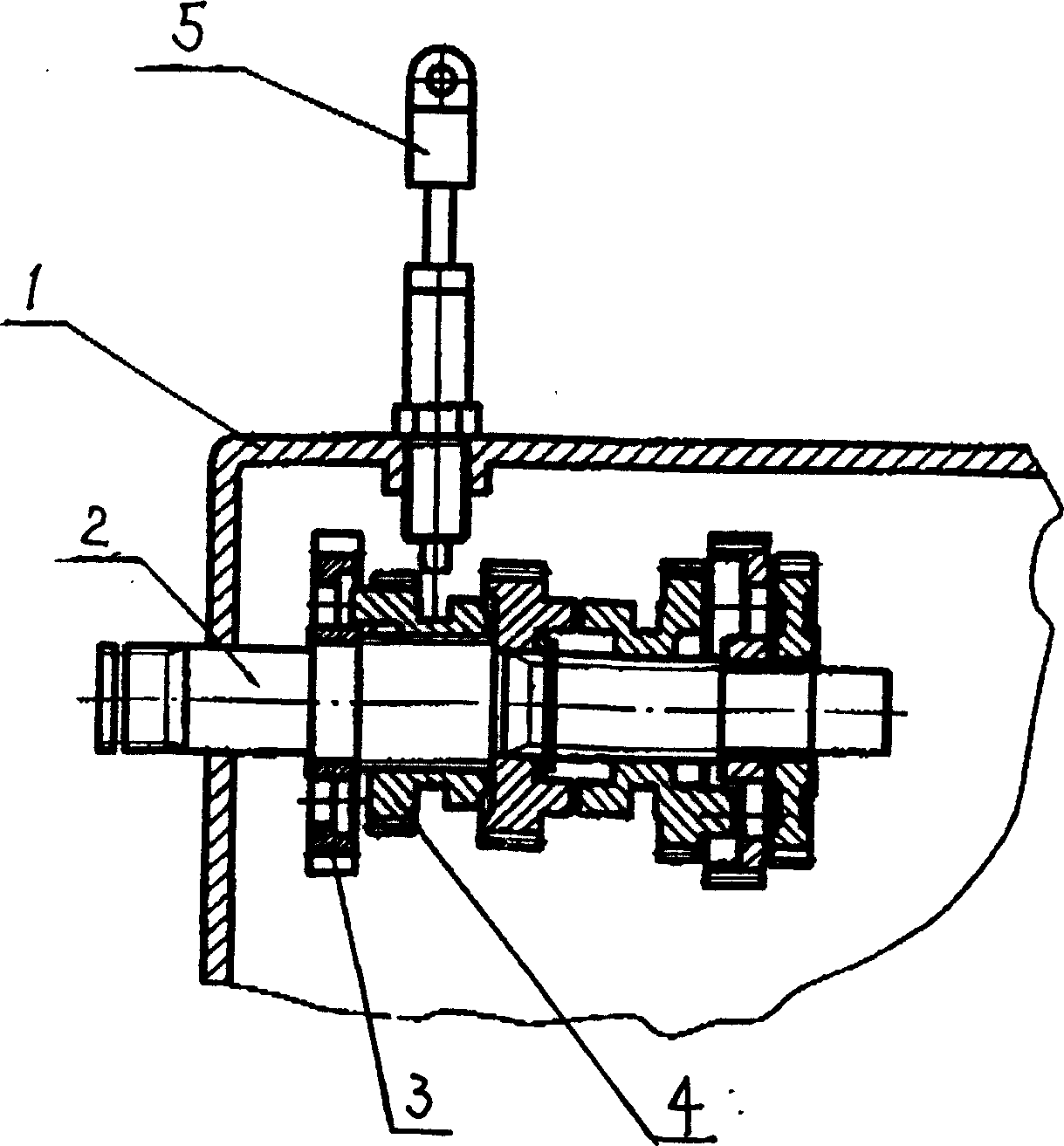
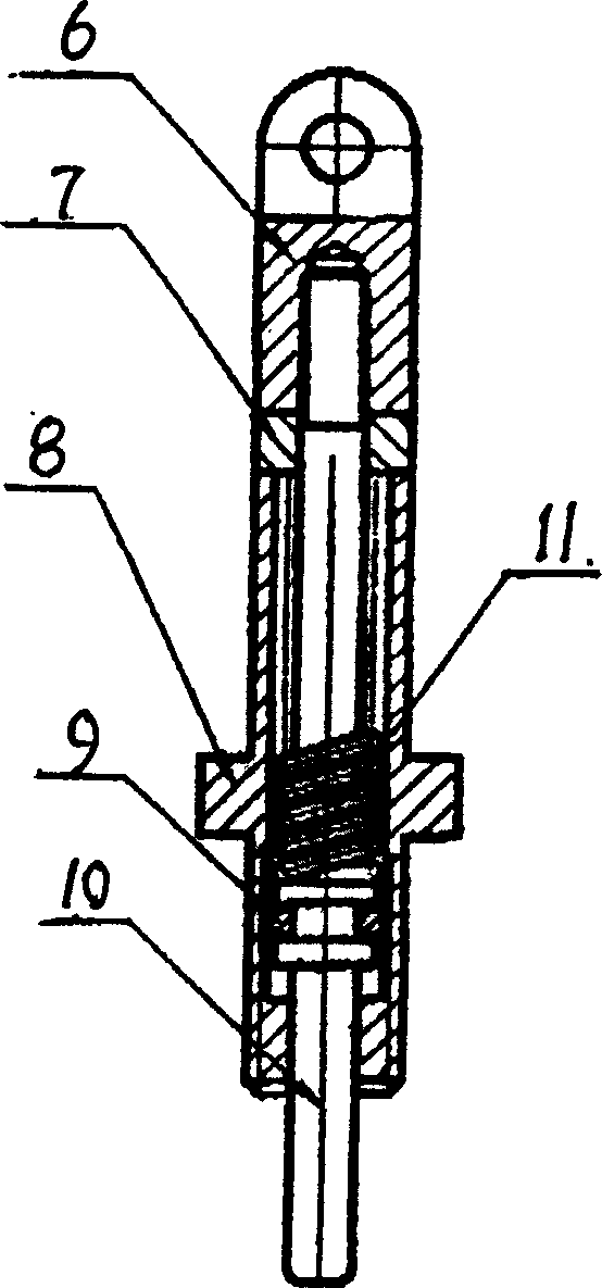
[0010] please see figure 1 , figure 2 , image 3 , the present invention is made up of starting left crankcase body 1, engine countershaft 2, reverse gear 3, fifth gear 4, reverse gear locking mechanism 5, wherein engine left crankcase body 1, countershaft 2 and are installed on the countershaft The reverse gear 3 and the fifth gear 4 on 2 are identical in structure with the prior art, but the difference is that the locking mechanism 5 installed on the engine crankcase 1 consists of a lock housing 8, an oil seal ring 9, a lock pin 10, a back Position spring 11, plug 7, handle 6, wherein the return spring 11 and oil seal ring 9 are set on the lock pin 10, and are located in the lock case 8, and one end of the lock pin 10 installed in the lock case 8 protrudes out of the lock case 8, the other end passes through the plug 7 and is fastened in the handle 6 (threaded connection can be used); the end of the lock pin 10 extending out of the lock housing 8 extends into the left cra...


PUM


Abstract

A mechanism that can lock the motorcycle engine reverse gear. Its feature is that the mechanism is made up of lock crust, oil sealing ring, lock-pin, return spring, bulkhead and handle. The return spring and the oil sealing ring are muff coupled in the lock-pin and are located in the lock crust. One end of the lock-pin equipped in the lock crust protrudes out of the lock crust and the other end protrudes through the bulkhead and tightly connects to the inside of the handle. The under-part of the lock crust is threaded coupled with the left crankcase body of the engine. The end that protruding out of the lock crust inserts into the shifting fork annular of the five steps gear on the auxiliary shaft of the engine. The advantages are simple structure, expediently and neatly to be operate.

Description

technical field [0001] The invention relates to a motorcycle engine, in particular to a motorcycle engine reverse gear locking mechanism. Background technique [0002] The reverse gear device is set on the motorcycle engine, which is beneficial to improve the operation and safety of the motorcycle. At present, the reverse gear of the motorcycle is realized by controlling the gear shift transmission on the main shaft and the auxiliary shaft through the gear change drum in the engine. The transmission drum is a cylinder with a groove on its circumference. The groove has a smooth section and a concave-convex deformation section. One end of the shift fork in the engine is located in the groove of the transmission drum, and the other is inserted into the transmission gear. When the shift drum rotates, the shift fork slides in its groove to drive the shift transmission of the gear. Existing motorcycles all control the rotation of the speed change drum by ...

Claims


Application Information

Patent Timeline
IPC IPC(8): B60K20/00F16H59/02F16H61/18
Inventor 尹明善杜江辛琪
Owner 力帆科技(集团)股份有限公司
Why Eureka
Try Eureka