Plate type heat exchanger

A heat exchanger and plate-bundle technology, applied in the fields of evaporators, reactors, plate heat exchangers, condensers, reboilers, and heat exchange devices, can solve the problem of high manufacturing precision, difficulty in handling, and plate heat exchangers. Uneven deformation and other problems, to achieve the effect of improving efficiency, light weight, and improving pressure bearing capacity

Inactive Publication Date: 2005-03-23
彭曦锋
View PDF6 Cites 20 Cited by
  • Summary
  • Abstract
  • Description
  • Claims
  • Application Information

AI Technical Summary

Problems solved by technology

However, this type of heat exchanger has the following disadvantages: First, because rubber or similar materials are used to seal between the plates through the locking force of the compression plate, the common disadvantage is that the pressure resistance of the device cannot be too large; Second, due to the limitation of the sealing material itself, this type of plate heat exchanger is not suitable for use in high temperature environments; third, due to its structural characteristics, it is difficult to reinforce the corner holes of the plates, and the seal between the corner holes and the plates The alignment of the groove is also difficult to handle, and its manufacturing is more difficult, and its manufacturing accuracy requirements are relatively large, and the equipment is prone to leakage due to insufficient reinforcement at the corner holes; Fourth, when the temperature and pressure differences between the heat exchange media are large When it is large, it is easy to cause uneven deformation between the plates, resulting in device failure; fifth, the trouble-free working life of the plate heat exchanger is relatively short due to the influence of the sealing material; sixth, because the flow rate of the heat exchanger depends on the The diameter of the inflow angle hole of the opened medium is limited to a certain extent when it is used for heat exchange of large flow medium; Seventh, the sealing periphery is too long, making the sealing reliability worse, and the pressure distribution performance cannot be too high; Eighth , because the heat exchange plate is thin, its bearing strength cannot be too high, so it is not suitable for heat exchange of high-pressure medium, let alone gas-gas medium heat exchange
Since this patent is welded as a whole along the length direction of the plate, the thermal compensation capability between the integrated plate core and the heat exchanger shell is poor. When the temperature difference between the two is large, the shell and the tube core may be Cracks will be formed due to large thermal stress, resulting in equipment leakage
Secondly, because this patent needs to be welded along the direction of the corrugation, the corrugations on the plate can only be linear, and the flow channel formed thereby can only be a linear channel, and the medium flows in this linear channel. It is easy to form laminar flow, which affects its heat transfer efficiency. It is estimated from the drawings and documents disclosed in this patent that its heat transfer efficiency may be lower than that of the existing mesh flow plate heat exchanger
Third, the plates in the patented structure, especially one side of the flow channel between the plates is also an unsupported structure, so when the pressure difference between the two heat exchange media is large, or the temperature difference between the two heat exchange media is large, It will cause the gap between the plates to change, further affect the heat transfer efficiency and effect, and even cause equipment damage, and because the plates are generally thin, their ability to resist deformation under pressure, stiffness and strength are poor
Fourth, this patent is not suitable for heat exchange of gaseous medium, because when the gaseous medium is exchanged, the heat exchange medium will condense and form a negative pressure in the condensing channel, which is undoubtedly a problem for plates with no supporting structure in the channel. Exacerbates the tendency of the plates to deform and even lead to complete failure of the device

Method used


Image

  • Plate type heat exchanger
  • Plate type heat exchanger
  • Plate type heat exchanger

Examples


Embodiment Construction

[0035] The present invention is explained in conjunction with accompanying drawing:

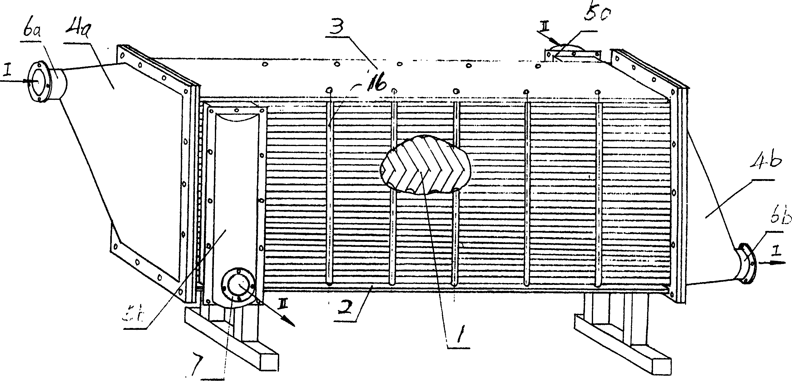
[0036] see figure 1 In the present invention, the plates 1 are permanently combined to form a heat exchange assembly 2 (that is, a heat exchange plate bundle). Fix with hold-down plate 3 and bolt 16 outside the board surface of outermost end. exist figure 1 In the example given, the flow guide boxes 4a, 5a and the combiner boxes 4b, 5b are arranged respectively at two mutually perpendicular ends of the bundle of plates of the module 2 .

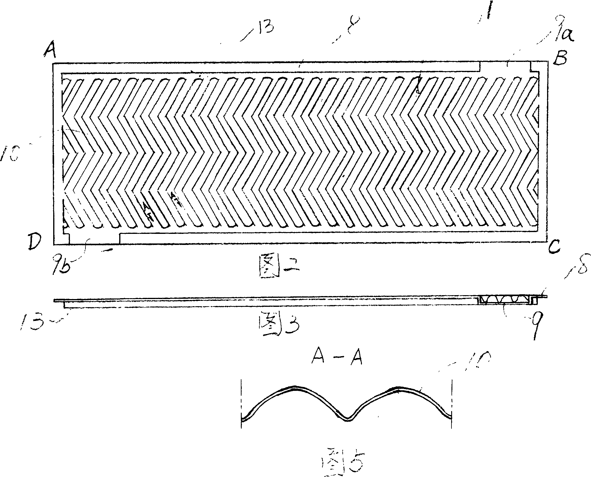
[0037] Fig. 2 is a corrugated plate-shaped first plate of the heat exchange plate 1 of the present invention, on which there are W-shaped corrugations 10, and there are folded edges 8 on the periphery of the plate 1, so that the plate 1 is A disc with a small rim. There are a section of gaps 9a and 9b at the folded edges of the diagonal positions of the plates, wherein 9a is located on the AB side of the plate 1, and 9b is located on the CD side of the p...


PUM


Abstract

The invention relates to a device which can carry on heat exchange between two kinds of media, especially is a board type heat exchanger. The board in the invention is pressed with W type, S type or V type corrugation, or linear corrugation slanted to the length direction of the board, there has upwards folding sides around the board, the opposite side of the board is arranged with a segment of gap for heat exchanging media flowing into the surface. Each board is arranged with two adjoined boards, forms the convex of corrugation on the board and they are contacted.

Description

technical field [0001] The invention relates to a device capable of exchanging heat between at least two media, especially a heat exchanging device in which the heat exchanging media are not in contact with each other. Specifically, the present invention is a plate-plate heat exchanger, condenser, evaporator, reboiler, or reactor. The present invention consists of at least four heat exchange components with corrugated plates permanently connected together, two compression plates arranged outside the heat exchange components, bolts for fixing the two compression plates, and heat exchange components It consists of at least two input devices and output devices that allow the heat exchange medium to enter or flow out of the heat exchange assembly. Background technique [0002] In order to solve many deficiencies of the shell and tube heat exchanger, a plate-fin heat exchanger was produced. For example: the plate heat exchanger shown in Japanese Patent No. Showa 61-276691, and ...

Claims


Application Information

Patent Timeline
Patent Type & Authority Applications(China)
IPC IPC(8): F28D9/02
Inventor 彭锁华
Owner 彭曦锋
Why Eureka
Try Eureka