Double-barrier tunnel junction senser having effect of resonance tunnel pass
A technology of resonant tunneling and double potential barriers, applied in the field of tunnel junction magnetic heads, can solve problems that have not been solved well
- Summary
- Abstract
- Description
- Claims
- Application Information
AI Technical Summary
Problems solved by technology
Method used
Image

Examples
no. 1 example
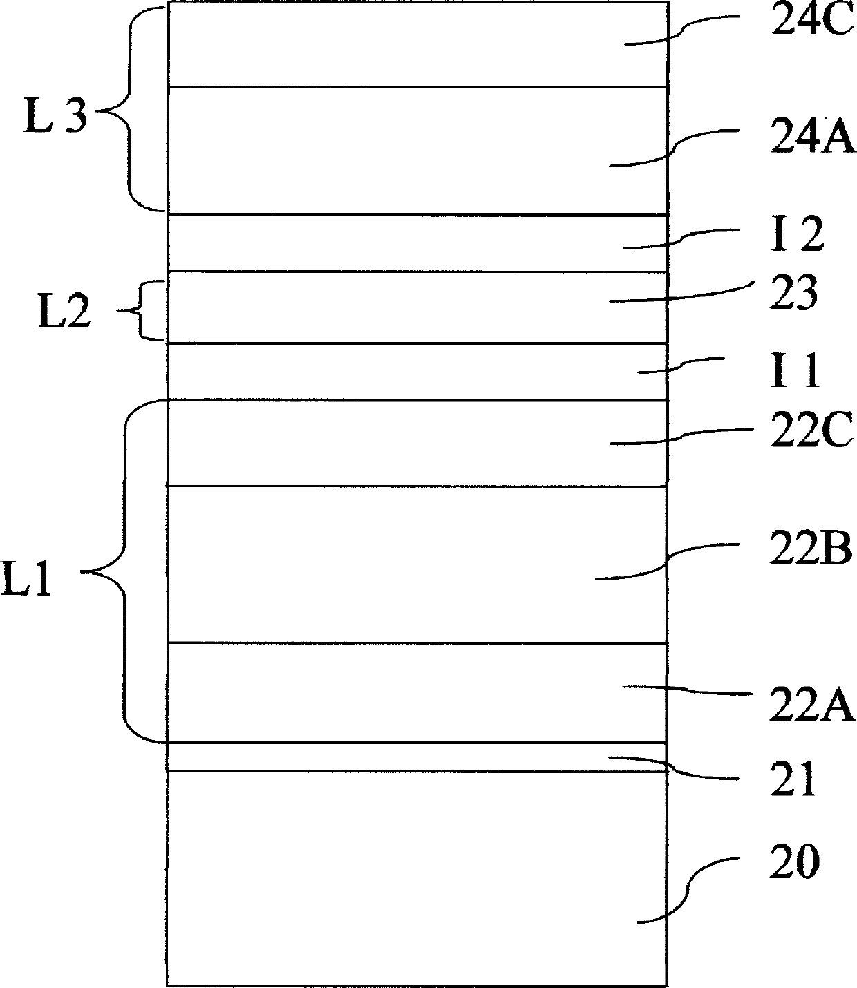
[0030] FIG. 4 shows the structure of the double-barrier tunnel junction with resonant tunneling effect according to the first embodiment of the present invention.
[0031] Figure 4, made of silicon dioxide (SiO 2) or similar material is formed on a silicon substrate 20, and a lower layer L1 is formed above the tunnel insulating layer 21, which consists of a ferromagnetic layer 22A, a ferromagnetic layer formed on the ferromagnetic layer 22A The upper antiferromagnetic layer 22B and a ferromagnetic layer 22C formed on the antiferromagnetic layer 22B, the magnetization direction of the lower layer L1 is fixed in position; a first layer formed on the ferromagnetic layer 22C Tunnel insulating layer I1, and an intermediate layer L2 is formed on the first tunnel insulating layer I1, which layer is made of non-magnetic metal or semiconductor; a second tunnel insulating layer I2 formed on the intermediate layer L2; a The upper layer L3 formed on the second tunnel insulating layer I2 ...
no. 2 example
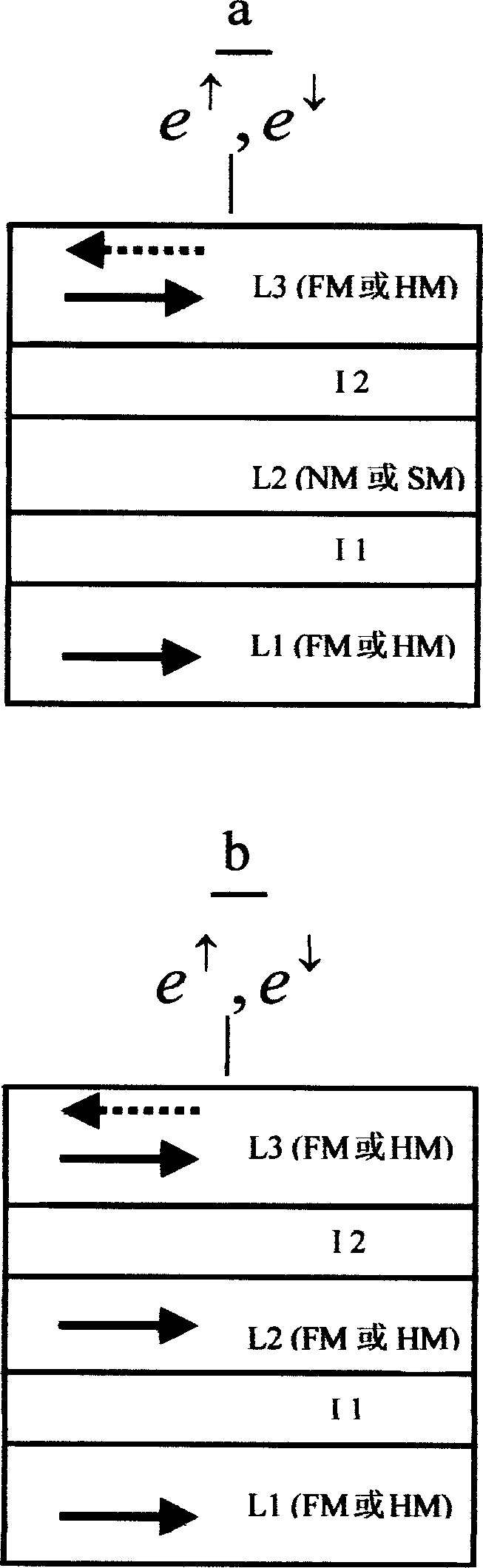
[0036] In the above embodiment, the magnetization direction of the upper layer L3 can be changed with the external magnetic field, while the magnetization direction of the lower layer L1 is fixed. Therefore, a thicker antiferromagnetic layer is formed under the ferromagnetic layer 22C. Layer 22B, however, will increase the surface roughness of layer 22C, and then when the first tunnel insulating layer I1 is formed on 22C, this surface roughness will affect their interface characteristics, thereby affecting the performance of the sensor. In view of the above problems, this embodiment proposes a double-barrier tunnel junction sensor in which the magnetization direction of the upper layer L3 is fixed and the magnetization direction of the lower layer L1 is free.
[0037] FIG. 5 shows the structure of a double barrier tunnel junction sensor with resonant tunneling effect according to the second embodiment of the present invention.
[0038] As shown in Figure 5, silicon dioxide (Si...
no. 3 example
[0042] It is known from early theory that the TMR value of the tunnel junction is related to the spin polarizability of the materials on both sides of the barrier, and the theory and experiments have proved that the spin polarizability of half-metallic magnetic materials is almost 100%, and the spin polarizability made of this material Double barrier tunnel junctions have higher TMR values. In view of this, the present embodiment provides a double-barrier tunnel junction sensor with resonant tunneling effect based on half-metallic magnetic materials.
[0043] The structure of the double barrier tunnel junction sensor of this embodiment is similar to that of the second embodiment. As shown in Figure 5, made of silicon dioxide (SiO 2 ) or similar material is formed on a silicon substrate 30, and a lower layer L1 is formed above the tunnel insulating layer 31, which is composed of a ferromagnetic layer 32A and a layer formed on the ferromagnetic layer 32A. The above half-metal ...
PUM
 Abstract
Description
Claims
Application Information