

Elastic track shoe
一种弹性体、弹性的技术,应用在履带车辆、机动车、运输和包装等方向,能够解决脱落、螺栓松弛、不能确保刚度等问题,达到提高刚性、增大容积、防止松弛或脱落的效果
- Summary
- Abstract
- Description
- Claims
- Application Information
AI Technical Summary
Problems solved by technology
Method used
Image

Examples
Embodiment Construction
[0035] Next, specific embodiments of the elastomer track shoe of the present invention will be described with reference to the drawings.
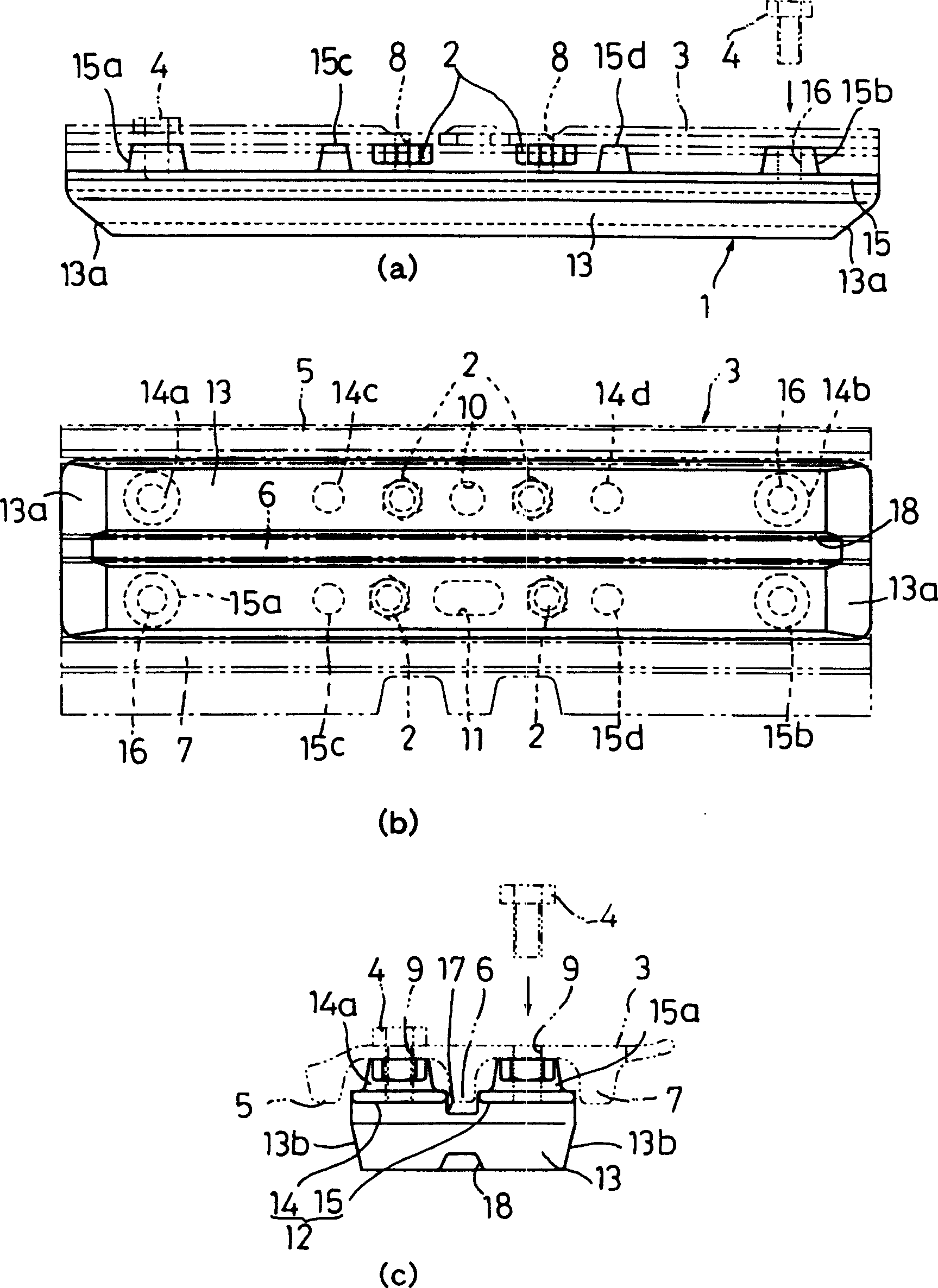
[0036] exist figure 1 In , a front view (a), a bottom view (b) and a side view (c) of the elastic body track shoe according to the first embodiment of the present invention are shown.
[0037] The elastic track shoe 1 of this embodiment is installed on the ground contact surface side of the iron track shoe 3 by a plurality of (four in this embodiment) bolts 4, and the iron track shoe 3 is There are four) bolts 2 and nuts (not shown in the figure) to be installed on the track link not shown in the figure.
[0038] The track shoe 3 has three gripping plates 5, 6, 7 in the central part and two side parts along the length direction of the tread. In addition, in the track shoe 3, a bolt insertion hole 8 for inserting the bolt 2 for mounting the track shoe 3 on the track link is provided at the central part, and at the same time, at positions n...
PUM
 Abstract
Description
Claims
Application Information